Normal-temperature high-frequency cavity inlet power measuring device and method

A technology of power measurement and high-frequency cavity, which is applied in the field of power measurement device of normal temperature and high-frequency cavity into cavity, can solve the problems of broken cavity, inability to accurately measure deflection angle, small coupling degree, etc., so as to improve measurement accuracy and facilitate power consumption. Monitoring and closed-loop control of low-level systems, reducing the effect of errors

Active Publication Date: 2020-04-17
INST OF HIGH ENERGY PHYSICS CHINESE ACADEMY OF SCI
View PDF6 Cites 2 Cited by
  • Summary
  • Abstract
  • Description
  • Claims
  • Application Information

AI Technical Summary

Problems solved by technology

The power and phase angle of the high-frequency cavity need to be locked during normal operation. The correct power and phase angle of the cavity are the prerequisites to ensure the effective acceleration of the beam. Otherwise, the beam will be damaged or even the cavity will be damaged by the beam.
When the cavity works at high power, its power loss into the cavity is very large (for example, in the Chinese spallation neutron source drift tube linear acceleration cavity, the inner wall loss is on the order of megawatts), and the outer low-level system coupling ring The measurable power is on the order of 1 watt, so the coupling ring is close to parallel to the magnetic field lines, and the coupling degree is very small, about 10 -6 order of magnitude, the deflection angle cannot be accurately measured, so the power into the cavity cannot be directly measured
[0003] The microwave power is transmitted to the high-frequency cavity through the coupling hole of the power coupler, because the power at the coupling hole (that is, at the entrance of the high-frequency cavity) cannot be directly measured. The existing power measurement method is through the forward power at the position of the directional coupler. The forward power and reflected power are measured by the meter and the reflected power meter respectively, and the measured forward power and reflected power are approximately equal to the actual forward power and reflected power at the entrance of the high-frequency cavity, but in practical applications, from the directional coupling A transmission line and a power coupler are also connected between the directional coupler and the entrance of the high-frequency cavity. Therefore, a certain amount of power loss will actually occur from the directional coupler to the high-frequency cavity, so the current measurement method cannot accurately obtain the power of the high-frequency cavity. Cavity power

Method used


Image

  • Normal-temperature high-frequency cavity inlet power measuring device and method
  • Normal-temperature high-frequency cavity inlet power measuring device and method
  • Normal-temperature high-frequency cavity inlet power measuring device and method

Examples


Embodiment 1

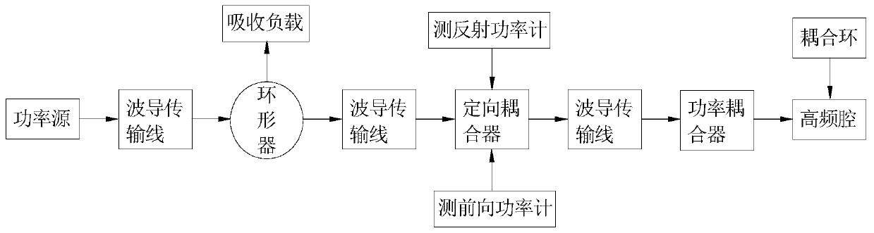
[0045] In this embodiment, a normal-temperature high-frequency cavity cavity power measurement device, such as figure 1 As shown, it includes a power source, a circulator, a directional coupler, a power coupler and a high-frequency cavity connected in sequence, among which, between the power source and the circulator, between the circulator and the directional coupler, and between the directional coupler and the power coupling The directional couplers are connected by waveguide transmission lines; the circulator is also equipped with an absorbing load, the high-frequency cavity is also equipped with a coupling ring, and the directional coupler is also equipped with a reflection power meter and a forward power meter. In the structure of the device, the directional coupler is similar to a transformer, and its main function is to take out a small part of the high microwave power for measurement by the reflected power meter and the forward power meter; the main function of the powe...

Embodiment 2

[0048] In this embodiment, a method for measuring the power of a room-temperature high-frequency cavity entering the cavity is realized by using the measuring device described in Embodiment 1.

[0049] The measurement method is to first calculate the entrance reflection coefficient of the high frequency cavity by measuring the field amplitude signal, phase angle signal and coupling degree of the high frequency cavity; then measure the reflected power and forward power of the directional coupler, and use the entrance reflection coefficient Calculate the power attenuation coefficient from the directional coupler to the entrance of the high-frequency cavity using the amplitude value; finally, use the power attenuation coefficient to calculate the forward power, reflected power and actual power entering the cavity at the entrance of the high-frequency cavity.

[0050] The concrete process of above-mentioned measurement method comprises the following steps:

[0051] S1: Collect the...


PUM


Abstract

The invention discloses a normal-temperature high-frequency cavity inlet power measuring device and method. The device comprises a power source, a circulator, a directional coupler, a power coupler and a high-frequency cavity which are connected in sequence. The power source and the circulator as well as the directional coupler and the power coupler are connected in sequence through waveguide transmission lines. The circulator is provided with an absorption load, the high-frequency cavity is provided with a coupling ring, and the directional coupler is provided with a reflection measuring power meter and a forward measuring power meter. The method comprises the following steps: calculating an inlet reflection coefficient of the high-frequency cavity by measuring a field amplitude signal, aphase angle signal and a coupling degree of the high-frequency cavity; measuring the reflection power and the forward power of the directional coupler, and calculating the power attenuation coefficient from the directional coupler to the inlet of the high-frequency cavity by utilizing the amplitude value of the reflection coefficient of the inlet; and finally, calculating the forward power, the reflection power and the actual cavity inlet power at the inlet of the high-frequency cavity by utilizing the power attenuation coefficient. According to the invention, the cavity inlet power of the high-frequency cavity can be accurately measured under high power.

Description

technical field [0001] The invention relates to the technical field of cavity power measurement, in particular to a device and method for measuring cavity power of a normal-temperature high-frequency cavity. Background technique [0002] Normal-temperature high-frequency cavities are often used to accelerate protons or heavy ions. Because they work at room temperature, most of the power entering the cavity is lost on the inner wall during the working process, and the power entering the cavity is usually on the order of kilowatts or even megawatts. , the whole high-frequency cavity system generally includes power source, transmission line, power coupler, high-frequency cavity and low-level control system. The power and phase angle of the high-frequency cavity need to be locked during normal operation. The correct power and phase angle of the cavity are the prerequisites to ensure the effective acceleration of the beam. Otherwise, the beam will be damaged or even the cavity wi...

Claims


Application Information

Patent Timeline
IPC IPC(8): G01R21/00
CPCG01R21/00
Inventor 王云刘华昌戴建枰李阿红吴小磊李波陈强樊梦旭瞿培华谢哲新慕振成
Owner INST OF HIGH ENERGY PHYSICS CHINESE ACADEMY OF SCI
Why Eureka
Try Eureka