High-voltage power supply circuit

A high-voltage power supply and circuit technology, applied in the direction of high-efficiency power electronic conversion, electrical components, adjusting electrical variables, etc., can solve the problem of dissipating large power consumption, and achieve the effect of improving efficiency, reducing loss, and improving EMI performance

Active Publication Date: 2020-04-17
MORNSUN GUANGZHOU SCI & TECH
View PDF10 Cites 3 Cited by
  • Summary
  • Abstract
  • Description
  • Claims
  • Application Information

AI Technical Summary

Problems solved by technology

However, the essence of this scheme is to use the resistance to generate a certain voltage automatic compensation. The difference caused by the discreteness of device parameters can only be compensated to a certain extent. As the difference increases, the resistance value of the resistance also needs to increase. As the power of the input power increases, the increased resistance will dissipate a large power consumption. At the time of power-on, the increased resistance acts as the ESR (equivalent series resistance) of the capacitor to a certain extent, so it will also bring EMI problem

Method used


Image

  • High-voltage power supply circuit
  • High-voltage power supply circuit
  • High-voltage power supply circuit

Examples


no. 1 example

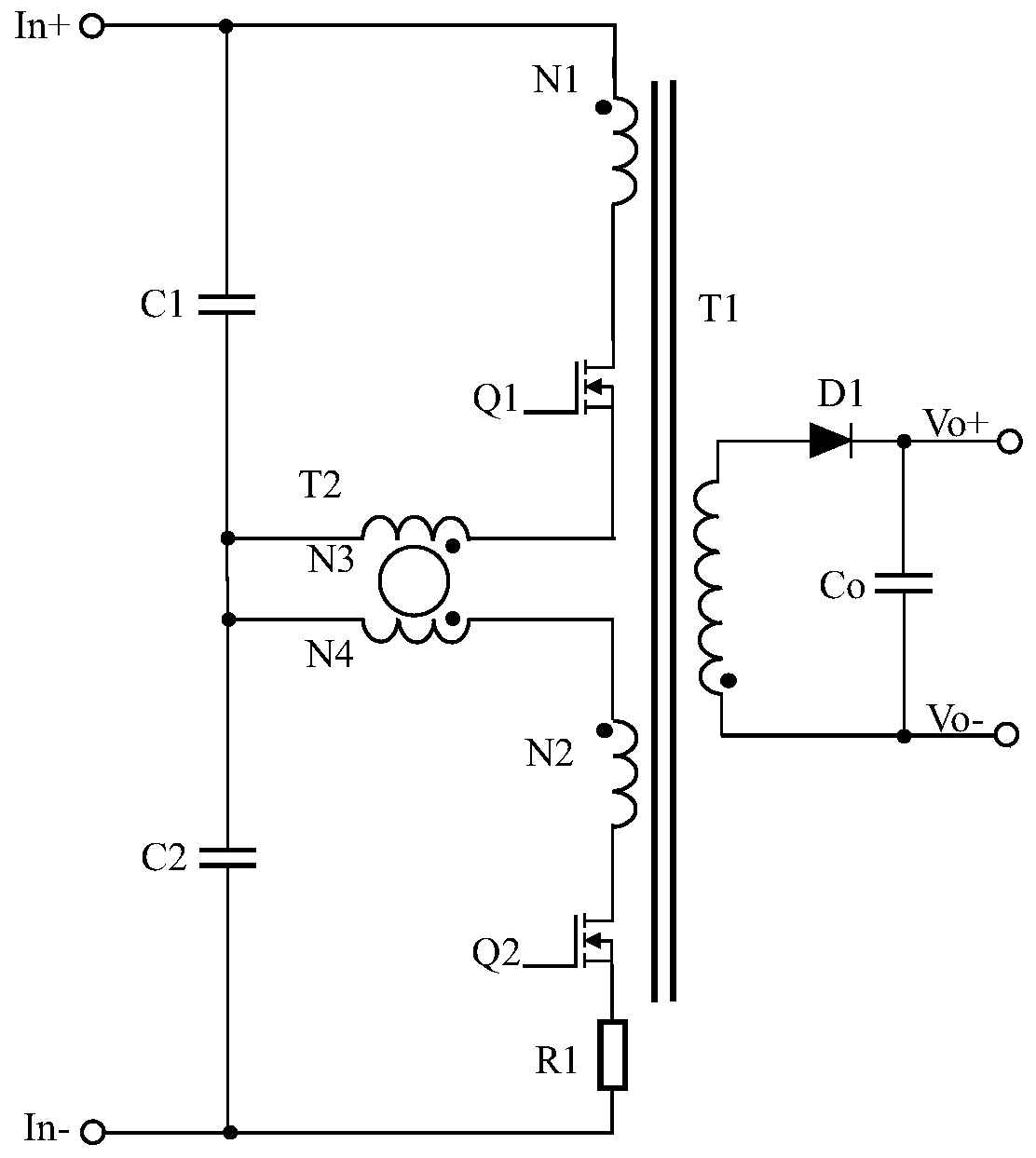
[0022] image 3 Shows the circuit diagram of the first embodiment, including the primary side composed of input voltage in+, input voltage in-, voltage equalizing transformer T2, first capacitor C1, second capacitor C2, first switching tube Q1, and second switching tube Q2 circuit, transformer T1, resistor R1, diode D1, and output capacitor Co to form the secondary side circuit. In the primary side circuit, the input voltage in+ is connected to one end of the capacitor C1, and the other end of the capacitor C1 is connected to one end of the capacitor C2, and at the same time connected to the opposite end of the third winding N3 and the opposite end of the fourth winding N4 in the equalizing transformer T2, The other end of the capacitor C2 is connected to the input voltage in-; the same-named end of the first winding N1 in the transformer T1 is connected to the input voltage in+, and the opposite-named end of the first winding N1 is connected to the drain of the switching tran...

no. 2 example

[0029] Figure 4 The circuit diagram of the second embodiment is shown, and the difference from the first embodiment is that this embodiment also includes a capacitor C3 and a capacitor C4, one end of the capacitor C3 is connected to the positive input terminal in+, and the other end of the capacitor C3 is connected to a voltage equalizing transformer The same-named end of the third winding N3 of T2, one end of the capacitor C4 is connected to the same-named end of the fourth winding N4 of the voltage equalizing transformer T2, and the other end of the capacitor C4 is connected to the negative input terminal in-.

[0030] This embodiment is a simple modification of the first embodiment, and its working principle is the same as that of the first embodiment, so details are not repeated here.

no. 3 example

[0032] Figure 5 The circuit diagram of the third embodiment is shown. The difference from the first embodiment is that the secondary side circuit includes a diode D1, a diode D2, an inductor L1 and a capacitor Co, and the connection relationship is as follows: the output winding of the transformer T1 is connected to The anode of the diode D1, the cathode of the diode D1 is connected to one end of the inductor L1, and its connection point is connected to the cathode of the diode D2, and the other end of the inductor L1 is connected to the positive pole of the output capacitor Co as the positive output terminal Vo+, the negative pole of the output capacitor Co and the diode D2 The anode is connected to the opposite end of the output winding of the transformer T1 as the negative output terminal Vo-.

[0033] The working principle of this embodiment is the same as that of the first embodiment, and will not be repeated here.

[0034] The transformer T1 works in a forward mode in ...


PUM


Abstract

The invention discloses a high-voltage power supply circuit. The high-voltage power supply circuit comprises a primary side circuit composed of a voltage-sharing transformer T2, a first capacitor C1,a second capacitor C2, a first switching tube Q1 and a second switching tube Q2, a transformer T1 and a secondary side circuit. Through the voltage-sharing transformer T2, the switching tube Q1 and the switching tube Q2 achieve automatic voltage balance, energy is transmitted to the secondary side circuit through the power transmission transformer T1, the voltage of the switching tubes is balancedin the energy transmission process, the efficiency and the EMI performance of the high-voltage power supply circuit are improved, and meanwhile the reliability of the high-voltage power supply circuit is effectively improved.

Description

technical field [0001] The invention relates to a high-voltage power supply circuit, in particular to a voltage equalizing circuit of a DC-DC or DC-AC high-voltage power supply circuit. Background technique [0002] With the rapid development of the new energy industry, electric vehicles, wind power, photovoltaic and other industries have more and more demands for switching power supplies with ultra-high and ultra-wide input voltage ranges, and the requirements are becoming more and more stringent. Charging piles in the electric vehicle industry use The power supply requires an input voltage range of 200VDC to 800VDC, and some require an upper limit of 1000VDC; the power supply products used in wind power and photovoltaic industries such as photovoltaic combiner boxes and inverters require an input voltage range of 150VDC to 1500VDC. As the voltage continues to increase, in order to solve the problem of excessive voltage stress of the switch tube of the power supply, among t...

Claims


Application Information

Patent Timeline
Patent Type & Authority Applications(China)
IPC IPC(8): H02M3/335H02M1/44
CPCH02M1/44H02M3/33569H02M1/0048Y02B70/10
Inventor 宋建峰俞伟军罗皓
Owner MORNSUN GUANGZHOU SCI & TECH
Why Eureka
Try Eureka