
Motor locked-rotor protection system, motor locked-rotor protection method and motor

A technology for motor stall and protection system, applied in control system, motor control, electrical components, etc., can solve problems such as customer complaints about property, power system unable to drive, IGBT ablation damage, etc., to improve the continuous torque value and duration , the effect of improving comfort and reliability

Pending Publication Date: 2020-04-17
JIANGLING MOTORS
View PDF5 Cites 3 Cited by
  • Summary
  • Abstract
  • Description
  • Claims
  • Application Information

AI Technical Summary

Problems solved by technology

When the car is running, it often encounters a wheel stall condition. At this time, the upper bridge arm of a certain phase IGBT of the UVW in the motor controller and the lower bridge arm of the other phase IGBT will continue to flow through a large Current, if the drive system does not have a reliable stall protection strategy, it may cause IGBT overheating and ablation damage due to high current, causing the power system to fail to drive, causing customer complaints and huge property losses

Method used


Image

  • Motor locked-rotor protection system, motor locked-rotor protection method and motor
  • Motor locked-rotor protection system, motor locked-rotor protection method and motor
  • Motor locked-rotor protection system, motor locked-rotor protection method and motor

Examples


Embodiment 1

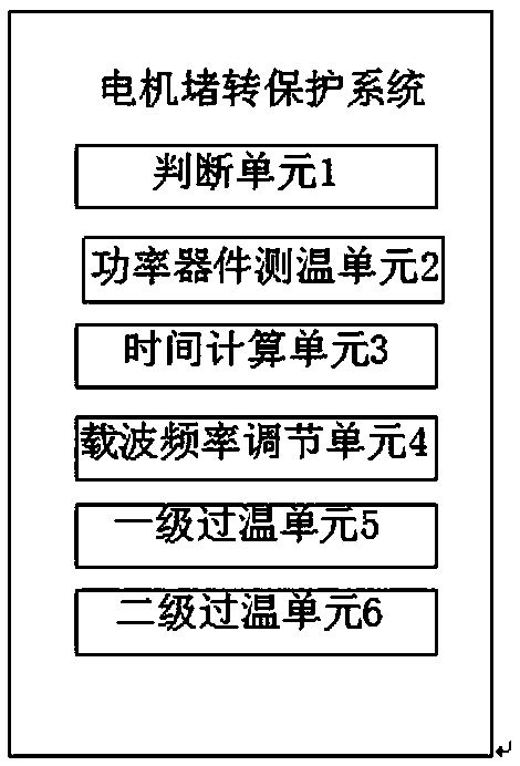
[0032] Such as figure 1 As shown, the embodiment of the present invention discloses a motor stall protection system, which is used for permanent magnet synchronous drive motors. Common stall protection strategies for permanent magnet synchronous motors mostly use the IGBT module junction temperature to estimate the temperature (hereinafter referred to as IGBT Temperature) as a single control variable, without accurate identification of the locked-rotor working condition, when the permanent magnet synchronous motor system continues to be locked-rotor output with a large torque, a large current will continue to flow through the IGBT, resulting in a rapid rise in the IGBT temperature, which will cause The system frequently triggers over-temperature faults, which greatly reduces the torque output, resulting in insufficient vehicle power and poor driving experience.

[0033] The IGBT (Insulated Gate Bipolar Transistor) here is an insulated gate bipolar transistor, which is a compos...

Embodiment 2

[0042] The protection system also includes a secondary over-temperature fault unit, which is signal-connected to the power device temperature unit, and is used to reduce the peak torque to zero when the measured temperature of the power device is within a certain range.

Embodiment 3

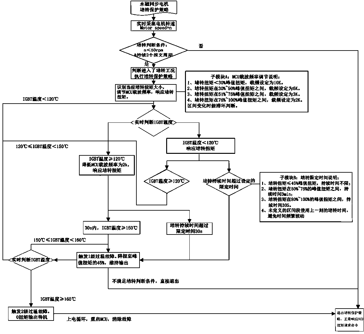
[0044] Such as figure 2 with image 3 As shown, this embodiment provides a motor stall protection method. Using the motor stall protection system, first set the following parameters: the peak torque of the motor is A1, the minimum carrier frequency for continuous operation of the peak torque is B, and the temperature of the power device is The first safe value C1 is 120°C, the second safe value is 150°C, and the third safe value is 160°C, and C1 corresponds to the first-level over-temperature fault, and the motor torque corresponding to the first-level over-temperature fault is A2 (45% of the peak torque ), secondary overtemperature fault.

[0045] Such as figure 2 As shown, the motor stall protection method includes the following steps:

[0046] It is judged that the motor enters the locked-rotor condition. The motor speed is collected in real time. When the speed signal lasts for two message periods and is <50rpm, it is judged to be in a locked-rotor condition.

[004...


PUM


Abstract

The invention discloses a motor locked-rotor protection system, a motor locked-rotor protection method and a motor. The motor comprises the motor locked-rotor protection system. The method comprises the following steps: judging that a motor enters a locked-rotor working condition; when the temperature of a power device is lower than C1, continuing peak torque to continue locked-rotor, setting thefirst safety time D1 of the continuous locked-rotor under C1, triggering a first-stage over-temperature fault when the continuous locked-rotor time exceeds D1, reducing the peak torque to A2, and maintaining output; and when the temperature of the power device is greater than or equal to C1, reducing a carrier frequency to B, and continuing the peak torque. According to the invention, by accurately identifying the locked-rotor working condition of the motor, the temperature of the power device, the switching carrier frequency of the power device and the locked-rotor limited time of the power device are real-timely monitored and dynamically adjusted based on different locked-rotor torques, so that the power device is reliably protected from over-temperature breakdown, the continuous torquevalue and the continuous time of the locked-rotor of the driving motor system are also improved, the sufficient power is provided for the whole vehicle, and the driving comfort and the reliability ofthe whole vehicle are improved.

Description

technical field [0001] The invention belongs to the technical field of automobiles, and in particular relates to a motor stall protection system, method and motor. Background technique [0002] New energy vehicles are developing vigorously. Most new energy vehicles in China use power batteries as the power source and are equipped with permanent magnet synchronous motor systems as the power drive mechanism. When the permanent magnet synchronous motor system is working, the power device IGBT in the motor controller will flow a large current. When the car is running, it often encounters a wheel stall condition. At this time, the upper bridge arm of a certain phase IGBT of the UVW in the motor controller and the lower bridge arm of the other phase IGBT will continue to flow through a large Current, if the drive system does not have a reliable stall protection strategy, it may cause IGBT overheating and ablation damage due to high current, causing the power system to fail to dri...

Claims


Application Information

Patent Timeline
IPC IPC(8): H02P29/024H02P29/68H02K11/25B60R16/02
CPCB60R16/02H02P29/024H02K11/25H02P29/68
Inventor 杨克文徐仕华翁顺苏磊昌
Owner JIANGLING MOTORS
Learn More