Pipeline sleeve joint welding process

A casing joint and welding process technology, applied in welding equipment, manufacturing tools, arc welding equipment, etc., can solve problems such as incomplete cleaning of impurities, fast cooling speed, and excessive current, so as to prevent thermal cracks from occurring and slow down Effect of cooling rate and attenuation of residual tensile stress

Active Publication Date: 2020-04-21
上海江南船舶管业有限公司
View PDF4 Cites 0 Cited by
  • Summary
  • Abstract
  • Description
  • Claims
  • Application Information

AI Technical Summary

Problems solved by technology

[0003] The above-mentioned existing technical solutions have the following defects: if there is a crack in the welded part of the pipe joint, there will be a danger of pipe leakage
The reasons for cracks are as follows: Incomplete cleaning of impurities before welding, excessive current during welding, and excessive cooling speed

Method used


Image

  • Pipeline sleeve joint welding process
  • Pipeline sleeve joint welding process
  • Pipeline sleeve joint welding process

Examples


Embodiment 1

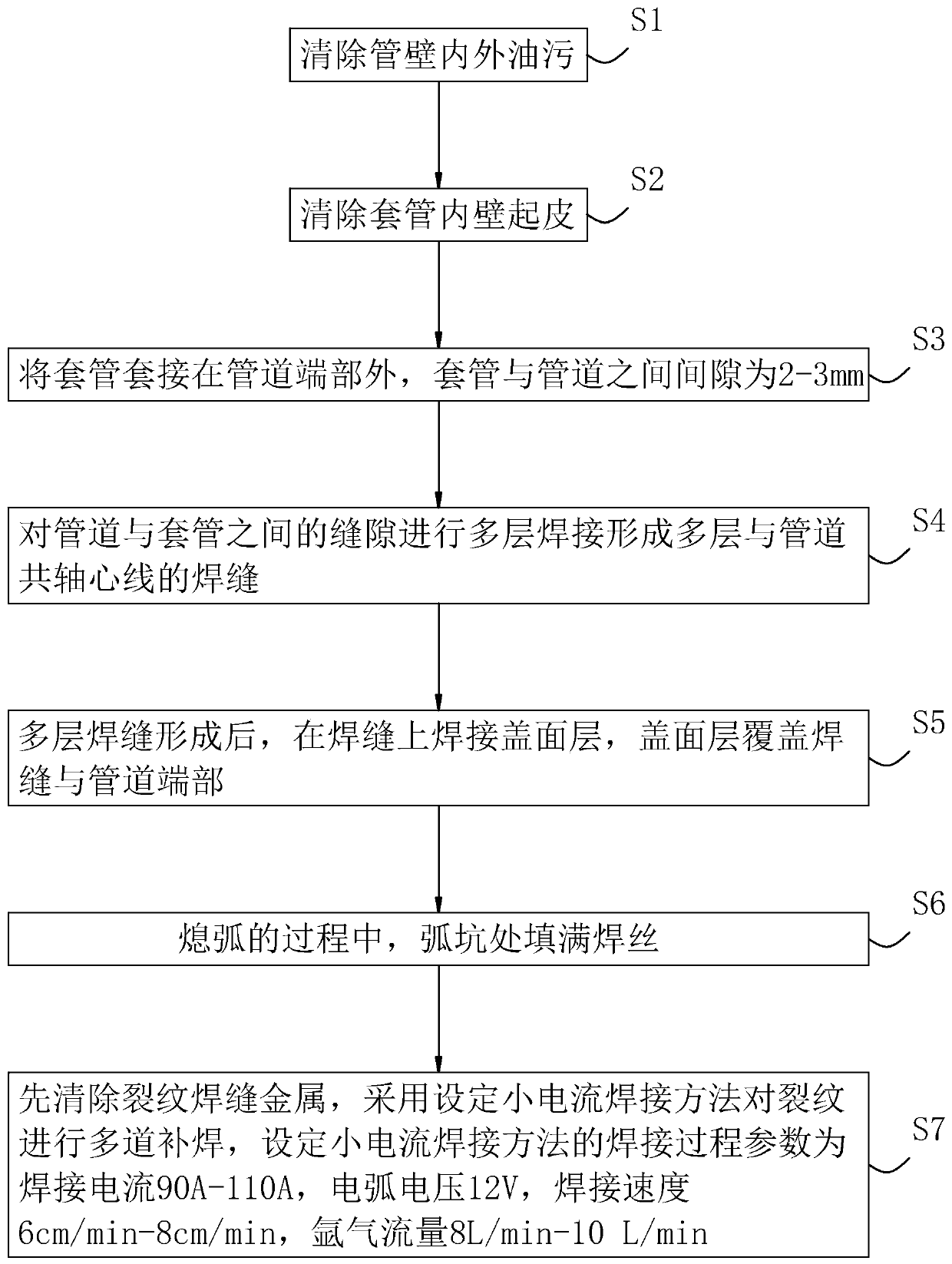
[0038] refer to figure 1 , is a casing joint welding process of a pipeline disclosed by the present invention, comprising the following steps:

[0039] S1: Remove oil stains inside and outside the pipe wall. Remove the oil, dust and other impurities inside and outside the pipe wall of the pipe 1, especially the oil left when the pipe is bent needs to be thoroughly cleaned, otherwise there will be bubbles, impurities, cracks in the weld, and the weld will not meet the standard.

[0040] S2: Remove the peeling on the inner wall of casing 2. Use an angle grinding wheel to remove the peeling phenomenon on the inner wall of the casing 2. If the peeling part cannot be completely removed, replace the casing 2 to prevent the generation of low melting point eutectics.

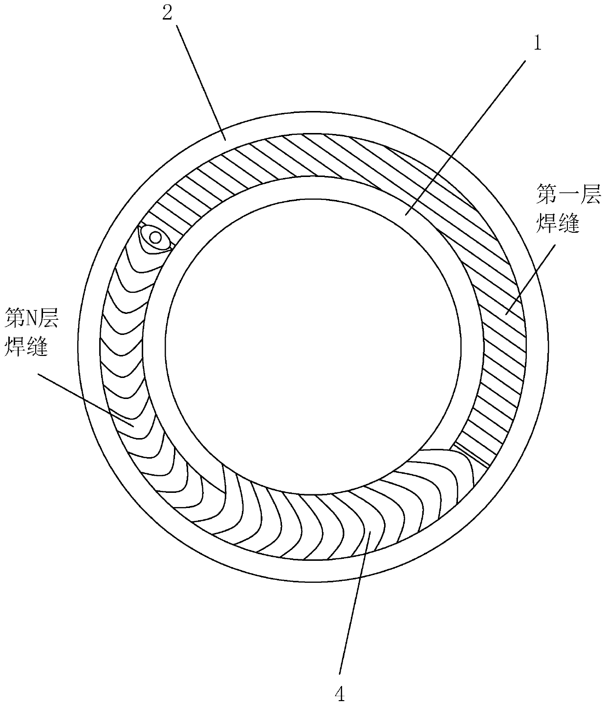
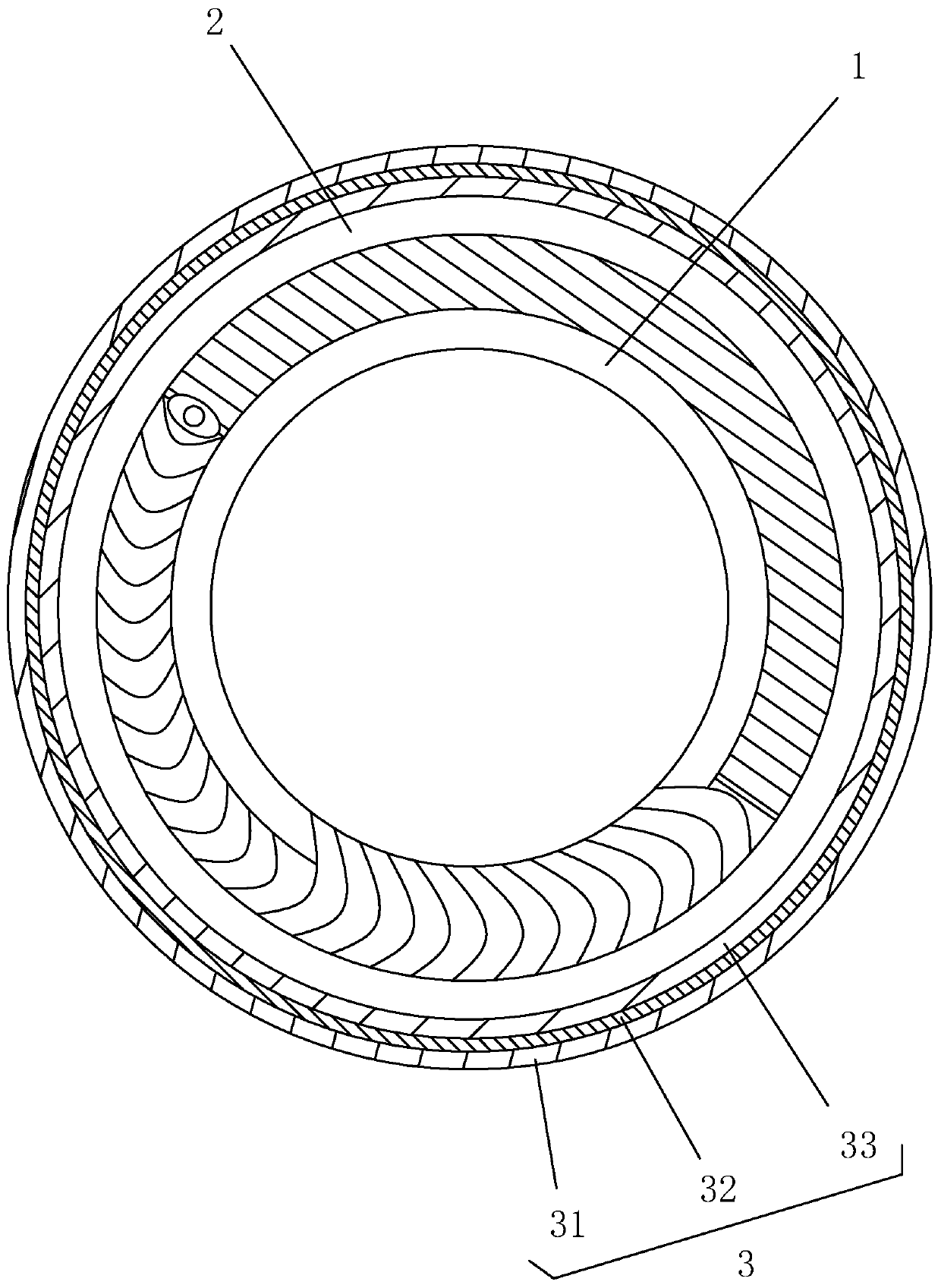
[0041] S3: Sleeve the sleeve 2 outside the end of the pipe 1, and the gap between the sleeve 2 and the pipe 1 is 2mm. Such as figure 2 and image 3 As shown, when welding, a layer of insulation pipe 3 is placed on...

Embodiment 2

[0048] A casing joint welding process for pipes, the difference from Embodiment 1 is that the gap between the casing 2 and the pipe 1 is 2.5mm. The welding process parameters in step S4 are as follows: first layer: welding current 110A, arc voltage 12V, welding speed 7cm / min, argon gas flow 9L / min; other layers: welding current 130A, arc voltage 15V, welding speed 5.5cm / min min, argon flow rate 11L / min. S7: First remove the cracked weld metal, and use the set low current welding method to repair the cracks in multiple passes. The welding process parameters of the low current welding method are set as welding current 100A, arc voltage 12V, welding speed 7cm / min, argon Air flow 9L / min. In multi-pass repair welding, the next repair welding is performed when the temperature after the previous repair welding drops to within 55°C.

Embodiment 3

[0050] A casing joint welding process for pipes, the difference from Embodiment 1 is that the gap between the casing 2 and the pipe 1 is 3 mm. The welding process parameters in step S4 are as follows: first layer: welding current 110A, arc voltage 12V, welding speed 8cm / min, argon gas flow rate 10L / min; other layers: welding current 130A, arc voltage 15V, welding speed 6cm / min , Argon gas flow rate 12L / min. S7: First remove the cracked weld metal, and use the set low current welding method to repair the cracks in multiple passes. The welding process parameters of the low current welding method are set as welding current 110A, arc voltage 12V, welding speed 8cm / min, argon The air flow rate is 10L / min. In multi-pass repair welding, the next repair welding is performed when the temperature after the previous repair welding drops to within 60°C.


PUM


Abstract

The invention relates to the technical field of pipeline welding, and discloses a pipeline sleeve joint welding process. The process comprises the steps that S1, oil stains inside and outside the pipewall are removed; S2, peeling of the inner wall of the sleeve is removed; S3, the end of the pipeline is sleeved with a sleeve, and the gap between the sleeve and the pipeline is 2-3mm; S4, multi-layer welding is conducted on the gap between the pipeline and the sleeve to form multiple layers of welding seams coaxial with the pipeline; S5, after the multiple layers of welding seams are formed, acover surface layer is welded to the welding seams, and the cover surface layer covers the welding seams and the end of the pipeline; and S6, arc pits are filled with welding wires in the arc extinguishing process. The generation of a low-melting-point liquid film is prevented, the welding tensile stress is reduced, the permeation of harmful substances is controlled, the residual tensile stress after welding can be effectively attenuated through multiple layers of welding, the cooling speed is reduced, the generation of hot cracks is prevented, slow arc extinguishing is realized, and the arc pits are filled with the welding wires to further prevent the generation of the hot cracks.

Description

technical field [0001] The invention relates to the technical field of pipeline welding, in particular to a welding process for casing joints of pipelines. Background technique [0002] Pipe joint welding is a common process in pipeline welding. In many cases, 1Cr18Ni9Ti austenitic stainless steel is used as the pipe fitting and casing material for pipe joint welding. It has the characteristics of small thermal conductivity and large linear expansion coefficient. produce greater thermal stress. [0003] The above-mentioned existing technical solutions have the following defects: if cracks appear in the welded parts of the pipe joints, there will be dangers of pipe leakage. The reasons for cracks are as follows: incomplete cleaning of impurities before welding, excessive current during welding, and excessive cooling speed. Contents of the invention [0004] In view of the deficiencies in the prior art, one of the purposes of the present invention is to provide a casing jo...

Claims


Application Information

Patent Timeline
IPC IPC(8): B23K9/028B23K9/235
CPCB23K9/028B23K9/0282B23K9/235
Inventor 冯旭东
Owner 上海江南船舶管业有限公司
Why Eureka
Try Eureka