
Cable plastic extrusion device

An extrusion device and plastic technology, applied to household components, household appliances, and other household appliances, etc., can solve the problems of segmental control at each stage, poor adaptability, single control of temperature parameters, flow rate parameters and pressure parameters, etc.

Inactive Publication Date: 2020-04-21
ANHUI FUXING CABLE GRP
View PDF7 Cites 4 Cited by
  • Summary
  • Abstract
  • Description
  • Claims
  • Application Information

AI Technical Summary

Problems solved by technology

[0002] The manufacture of cable insulation layer and sheath layer is generally completed by the cable plastic extrusion device used for cable production. The pressure and shear force generated by the cable plastic extrusion device through the rotation of the screw can make the materials fully plasticized and evenly mixed. , and then extrusion molding, by optimizing the temperature parameters, flow rate parameters and pressure parameters of the material during the extrusion process, it is suitable for different devices and materials of different materials, and can achieve the purpose of improving the quality of extruded cable plastics to meet the process requirements , but the existing cable plastic extrusion device can only single-control the temperature parameters, flow rate parameters and pressure parameters of the complete extrusion process, and cannot control each stage of the extrusion process in sections. To solve this problem, the existing cable The plastic extrusion device designs the screw segments in the device to be of different sizes and shapes, so as to adjust and control the temperature parameters, flow rate parameters and pressure parameters of the materials at different stages in the cable plastic extrusion process, but according to different materials and For different process requirements, it is necessary to adjust the use of screws with different segmental designs, which is difficult to operate and not strong in adaptability

Method used


Image

  • Cable plastic extrusion device
  • Cable plastic extrusion device
  • Cable plastic extrusion device

Examples


Embodiment Construction

[0035] In order to make the object, technical solution and advantages of the present invention clearer, the present invention will be described in further detail below in conjunction with specific embodiments and with reference to the accompanying drawings.

[0036] It should be noted that all expressions using "first" and "second" in the embodiments of the present invention are to distinguish two entities with the same name but different parameters or parameters that are not the same, see "first" and "second" It is only for the convenience of expression, and should not be construed as a limitation on the embodiments of the present invention, which will not be described one by one in the subsequent embodiments.

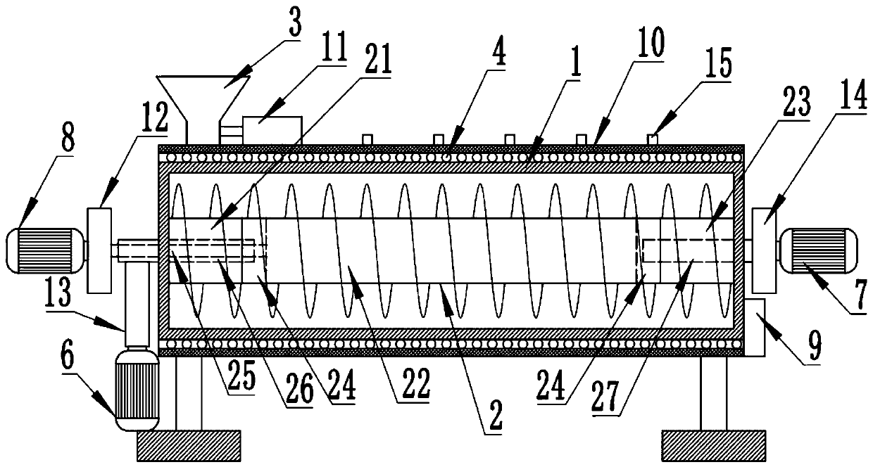
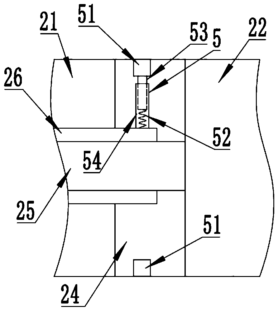
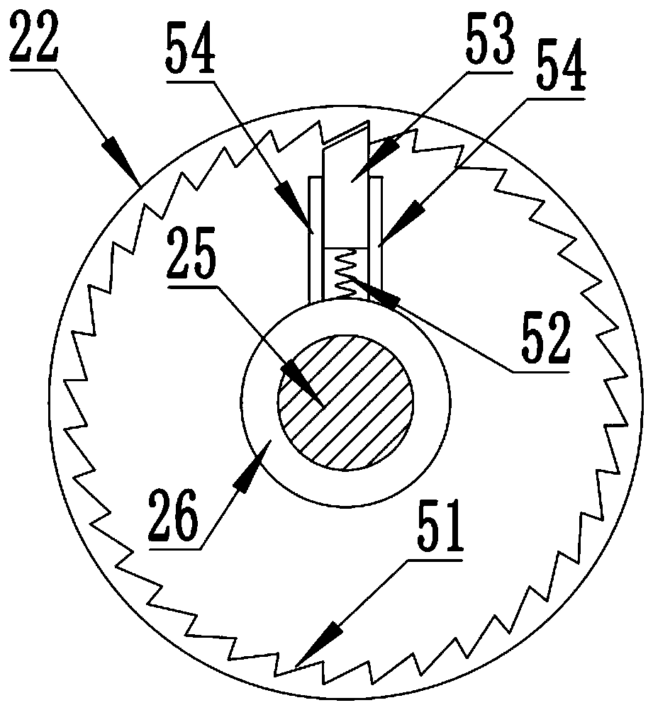
[0037] A cable plastic extrusion device such as Figure 1 to Figure 5 As shown, the barrel 1 is included, and the barrel 1 is provided with a screw 2. The screw 2 includes a feeding section screw 21, a melting section screw 22 and a discharging section screw 23 arrang...


PUM


Abstract

The invention discloses a cable plastic extrusion device. The cable plastic extrusion device comprises a charging barrel, wherein a screw rod is arranged in the charging barrel; the screw rod comprises a charging section screw rod, a melting section screw rod and a discharging section screw rod which are arranged in sequence; a feeding hopper is fixed at the upper end of the charging barrel; a heating device is arranged on the side wall of the charging barrel; acceleration mechanisms are symmetrically arranged in hollow cavities at the two ends of the melting section screw rod; a non-return pawl can only rotate in one direction relative to an inner ratchet wheel; a driving motor is controlled by a controller to drive the melting section screw rod to rotate; the non-return pawl and the inner ratchet wheel are reversely clamped and locked, and the inner ratchet wheel can drive the non-return pawl to rotate so as to drive the charging section screw rod and the discharging section screw rod to synchronously rotate; and the non-return pawl can rotate in the same direction relative to the inner ratchet wheel, so that a first acceleration motor and a second acceleration motor can be controlled by the controller to drive the non-return pawl to rotate in an acceleration mode in the same direction relative to the inner ratchet wheel so as to drive the charging section screw rod and the discharging section screw rod to rotate in an acceleration mode in the same direction relative to the melting section screw rod, and therefore, the acceleration rotation of the front section and the rear section of the screw rod can be controlled.

Description

technical field [0001] The invention relates to the technical field of cable processing equipment, in particular to a cable plastic extrusion device. Background technique [0002] The manufacture of cable insulation layer and sheath layer is generally completed by the cable plastic extrusion device used for cable production. The pressure and shear force generated by the cable plastic extrusion device through the rotation of the screw can make the materials fully plasticized and evenly mixed. , and then extrusion molding, by optimizing the temperature parameters, flow rate parameters and pressure parameters of the material during the extrusion process, it is suitable for different devices and materials of different materials, and can achieve the purpose of improving the quality of extruded cable plastics to meet the process requirements , but the existing cable plastic extrusion device can only single-control the temperature parameters, flow rate parameters and pressure param...

Claims


Application Information

Patent Timeline
Patent Type & Authority Applications(China)
IPC IPC(8): B29C48/395B29C48/80B29C48/25B29C48/505B29C48/76B29C48/285
CPCB29L2031/3462B29C48/252B29C48/287B29C48/397B29C48/505B29C48/767B29C48/832
Inventor 居盛文童天明方伟谷庆生吴云
Owner ANHUI FUXING CABLE GRP
Learn More