Optical fiber differential pressure sensing system with high static pressure and low differential pressure

A technology of differential pressure sensing and optical fiber sensor, which is applied to the measurement of pressure difference between multiple valves, the detection of fluid flow by measuring the pressure difference, and the use of optical devices to eliminate temperature drift, improve sensitivity, and improve measurement accuracy. Effect

Inactive Publication Date: 2020-04-21
UNIV OF ELECTRONICS SCI & TECH OF CHINA
View PDF5 Cites 3 Cited by
  • Summary
  • Abstract
  • Description
  • Claims
  • Application Information

AI Technical Summary

Problems solved by technology

There is no mature optical fiber differential pressure sensor product on the market now, based on this, the present invention proposes a highly sensitive high static pressure low differential pressure optical fiber differential pressure sensor

Method used


Image

  • Optical fiber differential pressure sensing system with high static pressure and low differential pressure
  • Optical fiber differential pressure sensing system with high static pressure and low differential pressure
  • Optical fiber differential pressure sensing system with high static pressure and low differential pressure

Examples


Embodiment 1

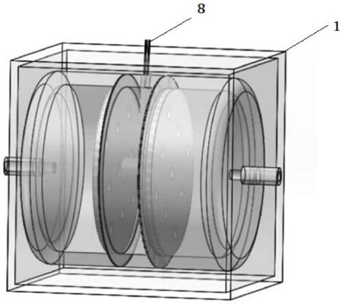
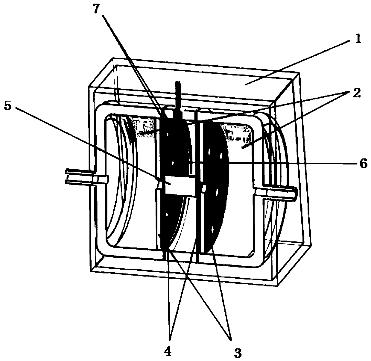
[0038] Such as Figure 1-Figure 2 As shown, a highly sensitive high static pressure and low differential pressure optical fiber differential pressure sensor of the present invention seals and divides the pressure pipe 2 into three chambers through two pressure sensitive diaphragms 4, and the third chamber in the middle adopts a connection The rod 5 is connected with two pressure-sensitive diaphragms 4, so that the pressure difference between the two chambers at both ends is converted into the displacement change of the connecting rod 5. By connecting a cantilever arm 6 to the connecting rod 5, when the displacement of the connecting rod 5 occurs The change causes the cantilever arm 6 to deform, and two optical fiber sensors 7 are used to measure the positive and negative deformation of the cantilever arm 6 to eliminate temperature drift, amplify the differential pressure drift to twice the original value, and improve the measurement accuracy of the sensor. The scheme adopted i...

Embodiment 2

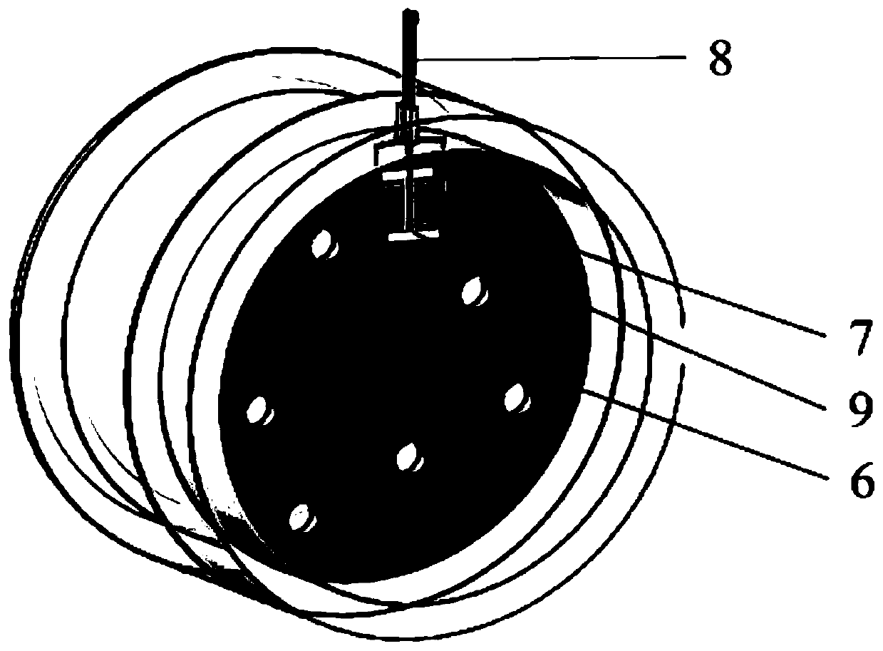
[0042] Such as Figure 4-Figure 5As shown, a high static pressure and low differential pressure optical fiber differential pressure sensing system of the present invention senses pressure through a pressure sensitive diaphragm 3, which reduces the process of intermediate transmission, and uses two optical fiber sensors 7 to pair the pressure sensitive diaphragm The deformation of 3 is measured positively and negatively, eliminating temperature drift, amplifying the differential pressure drift to twice the original value, and improving the measurement accuracy of the sensor. The scheme adopted is as follows:

[0043] An optical fiber differential pressure sensing system with high static pressure and low differential pressure, comprising a packaging case 1, and an optical fiber differential pressure sensing system located in the packaging case 1, the optical fiber differential pressure sensing system includes two optical fiber sensors 7. Pressure-sensitive diaphragm 4, two displ...


PUM


Abstract

The invention provides an optical fiber differential pressure sensing system with high static pressure and low differential pressure, which comprises a packaging shell and an optical fiber differential pressure sensing system located in the packaging shell, wherein the optical fiber differential pressure sensing system comprises two structures, differential pressure is converted into physical deformation through an optical fiber sensor, and the physical deformation is measured through the optical fiber sensor, so that the pressure difference is measured, and the measurement precision of the optical fiber differential pressure sensor can be effectively improved.

Description

technical field [0001] The invention belongs to the technical field of optical fiber sensing, in particular to an optical fiber differential pressure sensing system with high static pressure and low differential pressure. Background technique [0002] In the optical fiber sensing technology, the light propagating in the optical fiber senses the changes of various measured physical quantities in the outside world, and the measured information can be transmitted through the optical fiber. Due to the advantages of low cost, chemical corrosion resistance, anti-electromagnetic interference, and small transmission loss, optical fiber sensing has unique advantages in long-distance and complex environment measurements. In addition, with the rapid development of modern optoelectronic technology, various optoelectronic The emergence of devices has accelerated the application of optical fiber sensing in the engineering field, and has gradually entered people's lives. Compared with tra...

Claims


Application Information

Patent Timeline
Patent Type & Authority Applications(China)
IPC IPC(8): G01L13/02G01B11/16G01F1/34
CPCG01B11/18G01F1/34G01L13/025
Inventor 冉曾令李卓玥何正熙朱家良何鹏杨婷婷沈凤饶云江徐思捷向美琼吴茜
Owner UNIV OF ELECTRONICS SCI & TECH OF CHINA
Why Eureka
Try Eureka