Unsteady plasma excitation layout design method for inhibiting compressor stall

A plasma and unsteady technology, applied in the field of plasma, can solve the problem of insufficient stalling capacity of the compressor

Active Publication Date: 2020-04-21
AIR FORCE UNIV PLA
View PDF4 Cites 2 Cited by
  • Summary
  • Abstract
  • Description
  • Claims
  • Application Information

AI Technical Summary

Problems solved by technology

[0004] Aiming at the problem of insufficient ability of plasma excitation to suppress compressor stall in the prior art, the present invention designs an unsteady plasma excitation

Method used


Image

  • Unsteady plasma excitation layout design method for inhibiting compressor stall
  • Unsteady plasma excitation layout design method for inhibiting compressor stall
  • Unsteady plasma excitation layout design method for inhibiting compressor stall

Examples


Embodiment Construction

[0047] The present invention will be further described below in conjunction with the accompanying drawings.

[0048] 1. The determination method of the change law of the unsteady plasma excitation body force direction

[0049] At present, the research on the plasma flow control of compressor stall is mainly based on the sine wave DBD plasma excitation, and the plasma excitation used in the present invention refers to the sine wave DBD plasma excitation.

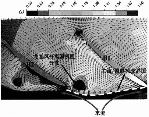
[0050] The invention uses numerical simulation and experiment, and the adopted experimental device includes a plasma power supply and a plasma excitation casing. The numerical simulation method provides the flow characteristics of the rotor tip near the stall point. Based on the flow characteristics of the rotor tip near the stall point, the unsteady plasma excitation layout is designed, and the plasma excitation casing is formed by processing. The plasma excitation casing is provided with a plasma power supply. High pressur...


PUM

PropertyMeasurementUnit
Thicknessaaaaaaaaaa
Thicknessaaaaaaaaaa

Abstract

The invention discloses an implementation method of an unsteady plasma excitation layout. The method comprises the steps of obtaining flow characteristics of a blade tip area of a compressor rotor under a near stall condition by utilizing numerical simulation; determining the change rule of the direction of the volume force formed by plasma excitation induction based on the flow characteristics ofthe blade tip area of the compressor rotor under the near stall condition; and obtaining a bent plasma excitation layout according to the curve of the function f(t). According to the method, an unsteady plasma excitation layout is designed on the basis of the flow characteristics of the rotor blade tip of the near-stall-point compressor, the direction of the plasma excitation induced volume forcecontinuously changes in the circumferential direction and is always perpendicular to the main/backflow interface, unsteady excitation of the flow field of the blade tip area of the compressor rotor is achieved, and thus efficient inhibition of compressor stall is achieved.

Description

technical field [0001] The invention relates to plasma technology, in particular to an unsteady plasma excitation layout design method for suppressing compressor stall. Background technique [0002] With the continuous increase of compressor stage pressure ratio and aerodynamic load, the strong reverse pressure gradient leads to more complex secondary flow and separation structure inside the compressor, often causing strong flow loss and blockage, and maintaining the necessary stall margin is become extremely difficult. In order to ensure sufficient stall margin for high-load compressors, many attempts have been made from the perspective of aerodynamic design, such as: low aspect ratio and high consistency design, curved and swept shape, large and small blades, etc. Because these passive control measures are difficult to effectively control the compressor stall in the full operating conditions of the engine, it is still a huge challenge to rely solely on it to break through...

Claims


Application Information

Patent Timeline
IPC IPC(8): H05H1/24F04D27/00
CPCH05H1/2406F04D27/00Y02T90/00
Inventor 张海灯吴云李应红
Owner AIR FORCE UNIV PLA
Why Eureka
Try Eureka