Parabolic grinding device

A parabola-shaped, grinding technology, applied in the direction of grain processing, etc., can solve the problems of large motor torque, large motor load, damage to the rotating shaft, etc., and achieve the effect of simple structure and sufficient grinding

Active Publication Date: 2020-04-24
四川瑞驰拓维机械制造有限公司
View PDF10 Cites 5 Cited by
  • Summary
  • Abstract
  • Description
  • Claims
  • Application Information

AI Technical Summary

Problems solved by technology

[0002] The traditional grinding equipment generally stirs through the rotating impeller and uses the mutual friction between the materials to achieve grinding and crushing. This grinding method does not grind the materials uniformly enough. At the same time, the traditional equipment fills the material box with the materials, and the required motor torque is also Relatively large, high power consumption, and when the processing volume is too large, it is easy to cause a large load on the motor, which will cause the shaft to be stuck and damaged

Method used


Image

  • Parabolic grinding device
  • Parabolic grinding device
  • Parabolic grinding device

Examples


Embodiment 1

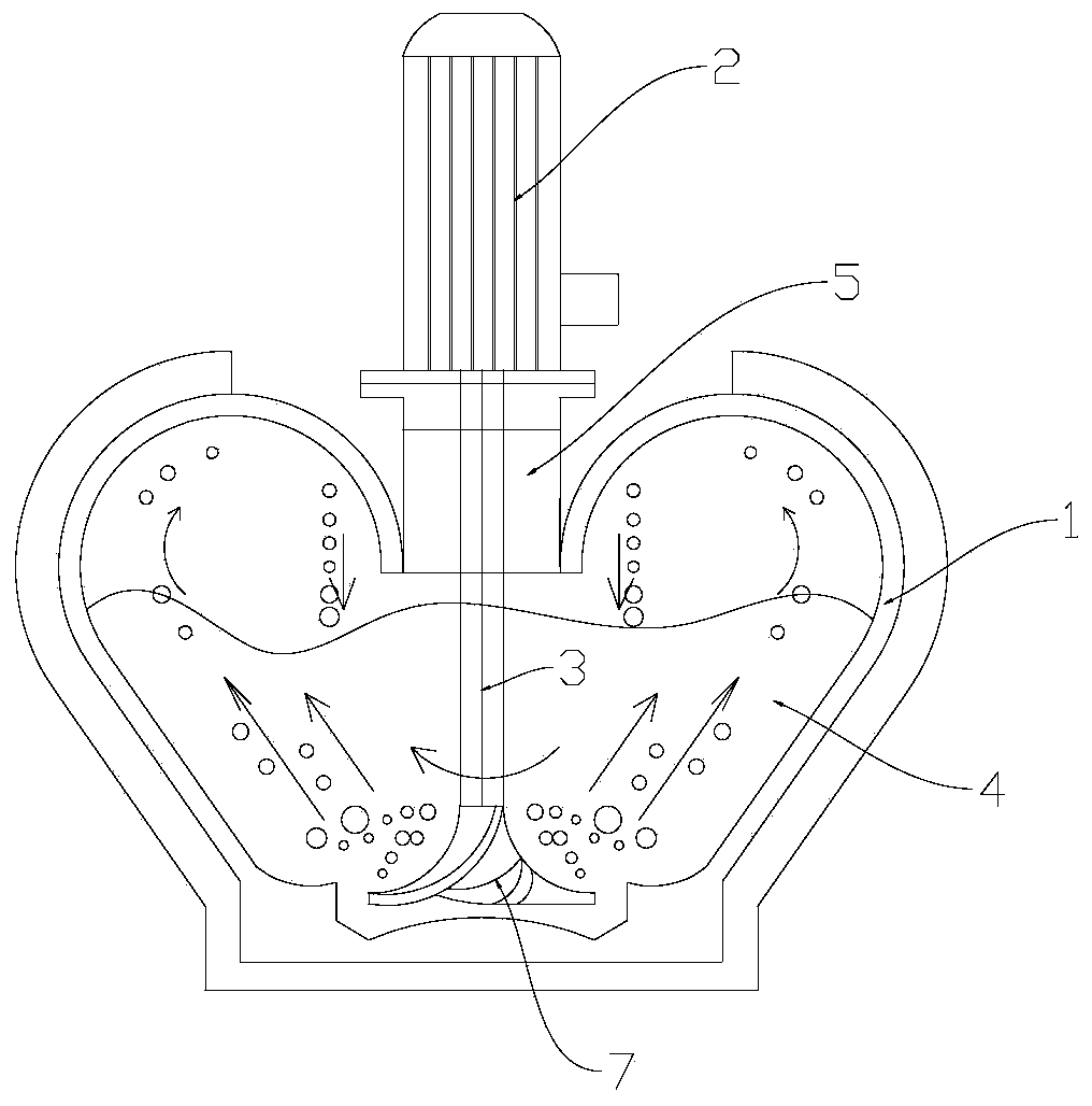
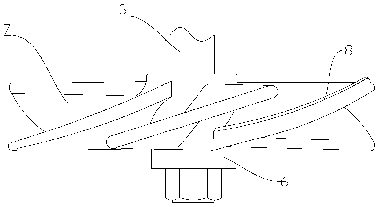
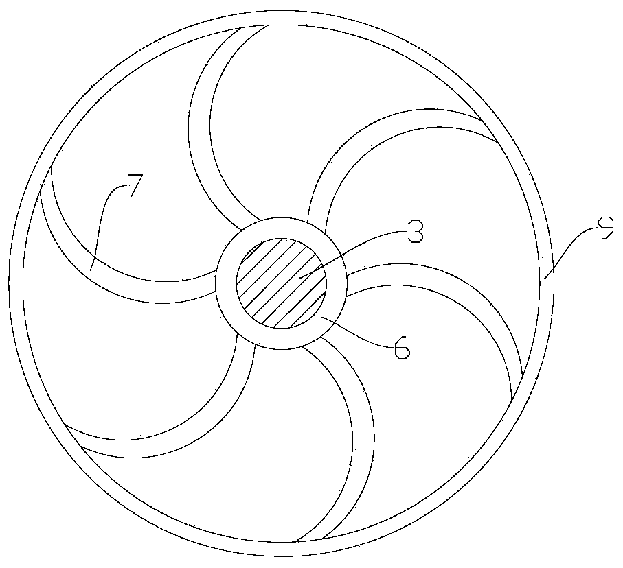
[0027] Please refer to Figure 1 to Figure 3 As shown, the present embodiment provides a parabolic milling device, including a grinding chamber 1, a motor 2 and a rotating shaft 3, the milling chamber 1 has a grinding chamber 4, and the milling chamber 4 has a parabolic parabolic wall surface, and the milling chamber 4 has a parabolic wall. Grinding chamber 4 is filled with granular grinding media. Grinding chamber 1 is provided with a feed inlet and a discharge outlet (not shown in the figure), and a filter screen is provided at the discharge outlet, and the feed inlet is higher than The discharge port and the grinding chamber 4 are made of wear-resistant materials such as wear-resistant alloys. The motor 2 is installed on the top of the grinding chamber 1. The output shaft of the motor 2 is connected to the rotating shaft 3 through a coupling 5, and the rotating shaft 3 extends to the bottom of the grinding chamber 4, the bottom end of the rotating shaft 3 is interference-fi...

Embodiment 2

[0033] Please refer to Figure 1 to Figure 5 As shown, this embodiment provides a parabolic mill, except for having all the technical features in Embodiment 1, the difference lies in that the outer wall of the grinding chamber 1 is provided with a cooling system. The cooling system includes a cooling jacket 10, a power supply 11, a cold water tank 12, a first U-shaped pipe 13 and a second U-shaped pipe 14, and the cold water tank 12 is sealed and connected to the cooling jacket 10 through a water delivery pipe 15. The water pipe 15 is provided with a solenoid valve 16, and the cooling jacket 10 is connected to the cold water tank 12 through the return pipe 17, and the water return pipe 17 is provided with a water pump 18, and the cooling jacket 10 is coated on the outer wall of the grinding chamber 1 to cool The sleeve 10 is made of a material with good thermal conductivity, such as a copper sleeve, an aluminum sleeve, and the like. Two sets of four holes are arranged symmetr...


PUM


Abstract

The invention relates to the technical field of grinding devices and discloses a parabolic grinding device comprising a grinding chamber, a motor and a rotary shaft. The grinding chamber is provided with a grinding cavity. The grinding cavity is provided with a parabolic wall face in a parabolic shape. The grinding cavity is filled with a granular grinding medium. The motor is arranged at the topof the grinding chamber. An output shaft of the motor is connected with the rotary shaft. The rotary shaft extends into the grinding cavity. Blades are evenly distributed at the lower end of the rotary shaft around the circumferential direction of the rotary shaft. Blade faces of the blades are curved faces warping upwards by a preset angle. A receiving disc and the blades warping upwards by the preset angle are arranged at the bottom of the grinding chamber, after materials are scattered to the receiving disc, the rotary shaft drives the receiving disc to rotate, the materials are thrown up by the blades, after thrown, the materials pass through the peach-shaped grinding cavity and are thrown back to the receiving disc along the outer wall of the grinding cavity, thus circular grinding ofthe materials is formed in the grinding cavity, and fuller grinding is achieved.

Description

technical field [0001] The invention belongs to the technical field of grinding devices, in particular to a parabolic grinding device. Background technique [0002] The traditional grinding equipment generally stirs through the rotating impeller and uses the mutual friction between the materials to achieve grinding and crushing. This grinding method does not grind the materials uniformly enough. At the same time, the traditional equipment fills the material box with the materials, and the required motor torque is also Relatively large, high power consumption, and when the processing volume is too large, it is easy to cause a large load on the motor, which will cause the shaft to be stuck and damaged. [0003] Therefore, how to solve the above problems has become the focus of research by those skilled in the art. Contents of the invention [0004] The first object of the present invention is to provide a parabolic mill, which solves the deficiencies in the prior art. [0...

Claims


Application Information

Patent Timeline
Patent Type & Authority Applications(China)
IPC IPC(8): B02C19/00B02C23/18
CPCB02C19/0031B02C23/18
Inventor 冯平仓彭静
Owner 四川瑞驰拓维机械制造有限公司
Why Eureka
Try Eureka