
Medium and small moving pump room floating on water surface

A pump room and water pump technology, which is applied in pumping stations, water supply devices, drinking water devices, etc., can solve the problems of sedimentation at water intake points, poor water quality, and rapid water level drop, etc., to achieve sufficient water intake and full use of energy , The effect of smooth water flow

Pending Publication Date: 2020-04-24
CAMCE WHU DESIGN & RES CO LTD
View PDF0 Cites 1 Cited by
  • Summary
  • Abstract
  • Description
  • Claims
  • Application Information

AI Technical Summary

Problems solved by technology

There are some problems in the construction of fixed pump houses: first, the large amount of engineering and high investment; second, after the heavy rain, the water intake point often deposits sediment and needs to be dredged frequently; third, for lakes, rivers, and ponds with small water areas, during the pumping process , the water level drops relatively quickly, and the amount of water taken is relatively small; the fourth is to take water from the shore, because there are many impurities in the water, the water needs to be filtered in multiple stages
The use of mobile pump trucks requires convenient transportation, manual maintenance is required for each operation, and there is also the problem of poor water quality, which is only suitable for small-area local irrigation and water intake

Method used


Image

  • Medium and small moving pump room floating on water surface
  • Medium and small moving pump room floating on water surface
  • Medium and small moving pump room floating on water surface

Examples


Embodiment 1

[0032] Example 1, such as Figure 5 As shown, a medium and small-sized mobile pump house floating on the water surface includes a floating warehouse 1, a water pump 2, a water pipe a3, a water pipe b4, a water pipe c5, a water pipe d6, a water pipe e7, a controller 12 and a water warehouse 14, and a floating warehouse 1 It has a closed cavity, and the water pump 2 is set on the floating chamber 1. One end of the water pipe a3 is connected to the water inlet of the water pump 2, the other end of the water pipe a3 extends into the water chamber 14, and the two ends of the water pipe b4 are respectively connected to the outlet of the water pump 2. The water outlet is connected to the water end, the two ends of the water pipe c5 are respectively connected with the water outlet of the water pump 2 and the cavity of the floating chamber 1, and the two ends of the water pipe d6 are respectively connected with the water inlet of the water pump 2 and the cavity of the floating chamber 1...

Embodiment 2

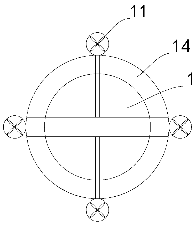
[0033] Example 2, such as figure 1 , figure 2 , Figure 5 As shown, the present embodiment is a further improvement carried out on the basis of embodiment 1, which is specifically as follows:

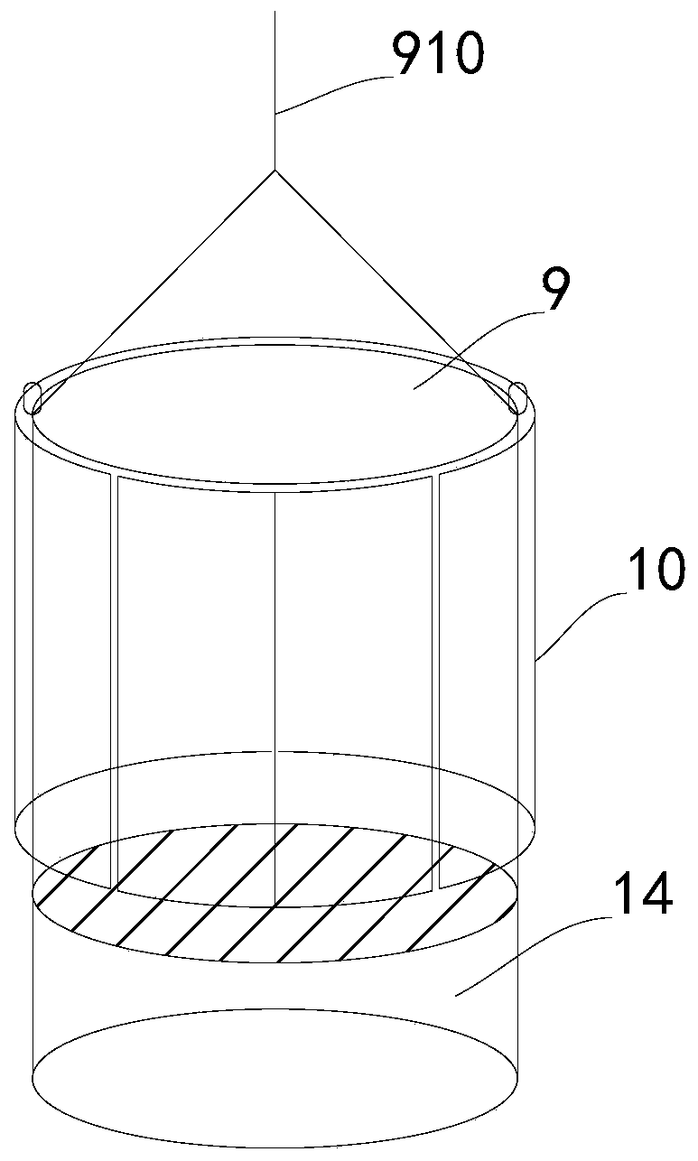
[0034] The medium and small mobile pump house floating on the water surface also includes a pump house main body 9, the pump house main body 9 is arranged on the floating chamber 1 and the water chamber 14, and floats on the water surface through the floating chamber 1, and the water pump 2 and the controller 12 are all set In the main body 9 of the pump room.

Embodiment 3

[0035] Example 3, such as figure 1 , figure 2 , Figure 5 As shown, the present embodiment is a further improvement carried out on the basis of embodiment 2, which is specifically as follows:

[0036] The medium and small mobile pump house floating on the water surface also includes a solar panel 10 and a storage battery, the solar panel 10 is arranged on the main body 9 of the pump room, the solar panel 10, the water pump 2, the controller 12, the solenoid valve a310, and the solenoid valve b410 , solenoid valve c510, solenoid valve d610, and solenoid valve e710 are electrically connected to the battery respectively. Of course, in the actual construction process, it is not ruled out that wind power generation is used instead of solar power generation, or wind power generation and solar power generation coexist. In addition, 220V two The phase power, usually, is mainly powered by the solar panel 10, which can make full use of energy and reduce the operating cost of the pump...


PUM


Abstract

The invention relates to a medium and small moving pump room floating on a water surface. The pump room comprises a floating vessel, a water pump, a water pipe a, a water pipe b, a water pipe c, a water pipe d, a water pipe e, a controller and a water sump. The water pump is mounted on the floating vessel, one end of the water pipe a is connected with a water inlet of the water pump, the other endof the water pipe a extends into the water sump, the two ends of the water pipe b are connected with a water outlet and a water using end of the water pump correspondingly, the two ends of the waterpipe c communicate with the water outlet of the water pump and a cavity of the floating vessel correspondingly, the two ends of the water pipe d communicate with the water inlet of the water pump andthe cavity of the floating vessel correspondingly, one end of the water pipe e is connected with the water outlet of the water pump, the other end of the water pipe e extends into the water sump, an electromagnetic valve a, an electromagnetic valve b, an electromagnetic valve c, an electromagnetic valve d and an electromagnetic valve e which are electrically connected with the controller are mounted on the water pipe a, the water pipe b, the water pipe c, the water pipe d and the water pipe e correspondingly, and the water pump is electrically connected with the controller. The water getting depth can be adjusted along with water level changes and water quality changes, the water getting amount is sufficient, the water quality is good, and the water treatment cost is correspondingly reduced.

Description

technical field [0001] The invention relates to the field of agricultural irrigation, in particular to a medium and small mobile pump house floating on the water surface. Background technique [0002] In the process of agricultural irrigation, it is often necessary to take water from lakes, rivers, and ponds and transport it to the water demand terminal. Most of the current methods are to build a fixed pump house near lakes, rivers, ponds or on the bank, or to use mobile pump trucks to pump water for irrigation. There are some problems in building a fixed pump house: first, the amount of work is large and the investment is high; second, after the heavy rain, the water intake point is often silted up with sediment and needs to be dredged frequently; third, for lakes, rivers, and ponds with small water areas, during the pumping process , the water level drops relatively quickly, and the amount of water taken is relatively small; the fourth is to take water from the shore, bec...

Claims


Application Information

Patent Timeline
Patent Type & Authority Applications(China)
IPC IPC(8): E03B5/00E03B3/04E03B7/07
CPCE03B3/04E03B5/00E03B7/074
Inventor 吴争光杨琳吴光星
Owner CAMCE WHU DESIGN & RES CO LTD
Learn More