
Flue gas afterburning type waste heat steam injection boiler, method and system for producing high-pressure superheated steam

A technology of superheated steam and flue gas, which is applied in the field of supplementary-fired steam injection boilers, which can solve problems such as difficulty in producing steam with higher pressure levels

Pending Publication Date: 2020-04-24
宋阳
View PDF7 Cites 1 Cited by
  • Summary
  • Abstract
  • Description
  • Claims
  • Application Information

AI Technical Summary

Problems solved by technology

[0005] Aiming at the problem that it is difficult to produce high-pressure steam with the waste heat of flue gas from gas turbines and gas internal combustion engines, the application of the "direct-flow" form in waste heat boilers, this application provides a flue gas supplementary combustion type waste heat steam injection for producing high-pressure superheated steam Boilers, methods and systems

Method used


Image

  • Flue gas afterburning type waste heat steam injection boiler, method and system for producing high-pressure superheated steam
  • Flue gas afterburning type waste heat steam injection boiler, method and system for producing high-pressure superheated steam
  • Flue gas afterburning type waste heat steam injection boiler, method and system for producing high-pressure superheated steam

Examples


Embodiment 1

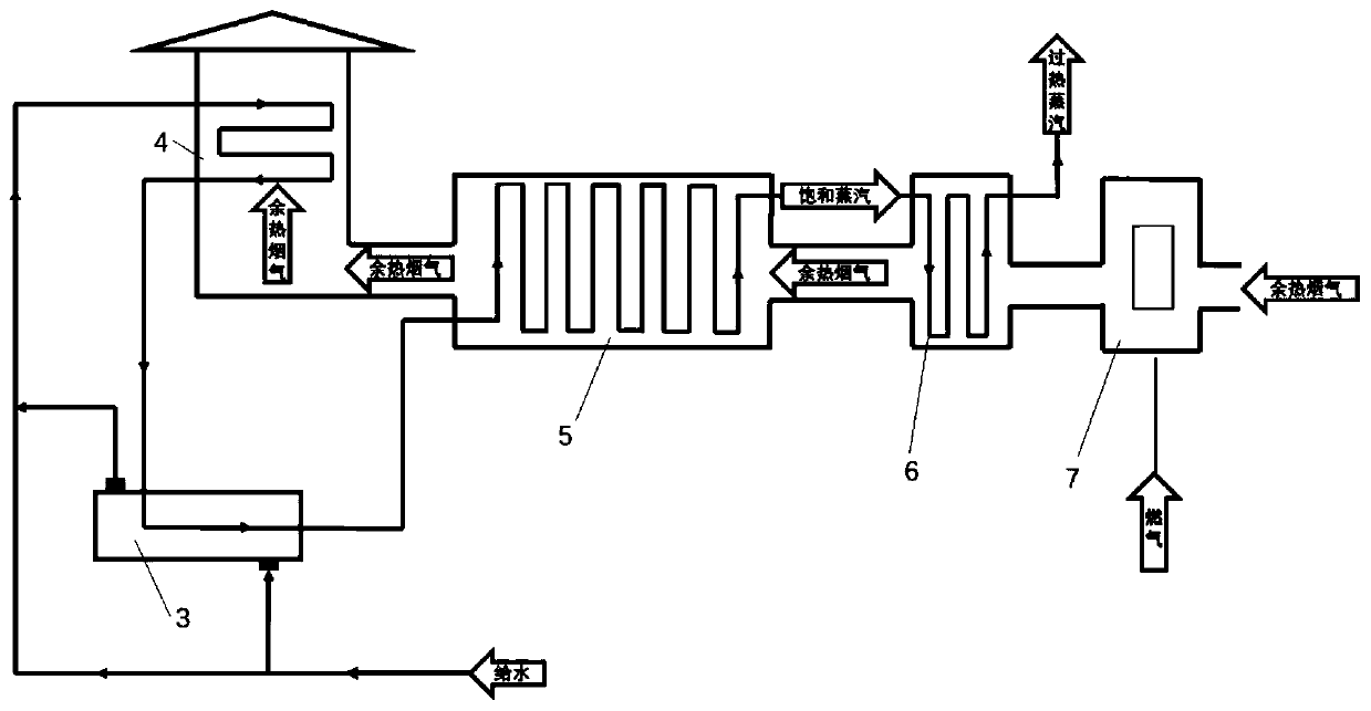
[0072] refer to figure 1 , this embodiment provides a flue gas supplementary combustion type waste heat steam injection boiler for producing high-pressure superheated steam, including: an economizer 4, a feed water preheater 3 (optional), a furnace 5, and the entrance of the flue gas channel of the furnace , a flue is provided, and the flue is followed by a superheating section 6 and a supplementary combustion section 7. It should be understood that the superheating section 6 can also be replaced by a superheater, or the superheater is arranged in the flue, and the post-combustion section 7 includes a post-combustion burner, and the post-combustion burner is located in the flue.

[0073] The chamber of the economizer 4 is provided with a water pipe through which water is supplied and water inlets and outlets at both ends of the water pipe. The chamber is also provided with a flue gas inlet and a flue gas outlet. The water pipe exchanges heat with the flue gas in the chamber th...

Embodiment 2

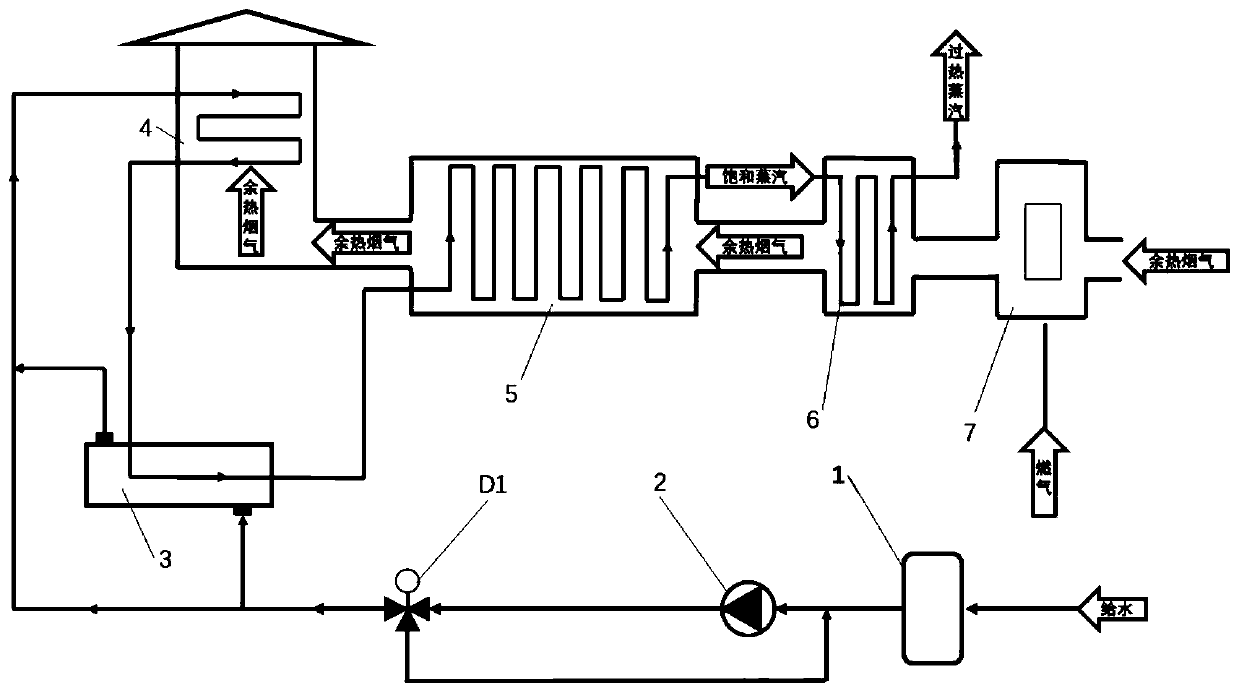
[0084] refer to figure 2 And embodiment 1, this embodiment provides a system for producing superheated steam, including water supply equipment 1 , pressurization equipment 2 , feedwater preheater 3 , economizer 4 , and furnace 5 .

[0085] The water supply equipment 1 includes a water supply pipeline for providing demineralized water. The pressurization equipment 2 is located on the water supply pipeline for pressurizing the demineralized water. Downstream of the pressurization equipment, the water supply pipeline is divided into a first water supply branch and a second water supply A branch, the first feedwater branch passes through the feedwater preheater 3 , and the part of the first feedwater branch inside the feedwater preheater 3 forms a first channel. The first feedwater branch and the second feedwater branch merge downstream of the feedwater preheater 3 and enter the water inlet of the economizer 4 together.

[0086] The water outlet of the economizer 4 is connected ...

Embodiment 3

[0091] In this embodiment, the flue gas comes from a gas turbine. The gas consumption of a 6630kW gas turbine of a certain brand is 2059Nm 3 / h, power generation efficiency is 32.2%, according to gas calorific value 35.5MJ / Nm 3 Calculated, including mechanical loss and other irreversible losses, there are 13766kWh (67.8%) of energy per hour that cannot be effectively utilized.

[0092] Taking the steam data required for heavy oil production in an oilfield in Xinjiang as an example, the steam demand is 10MPa high-pressure saturated steam. The flue gas waste heat steam injection boiler of this application is matched with the 6630kW gas turbine of this brand. The 505°C high temperature flue gas generated by the gas turbine power generation has a flow rate of 93153kg / h and enters the furnace of the flue gas supplementary combustion type waste heat steam injection boiler of this application. Initially The feed water temperature is 20°C, and the exhaust gas temperature of the econ...


PUM


Abstract

The invention discloses a flue gas afterburning type waste heat steam injection boiler, method and system for producing high-pressure superheated steam. Flue gas waste heat generated by gas turbine power generation and the like can be fully utilized, and the part of energy is recycled in a "once-through" waste heat boiler mode, so that production of high-pressure or ultrahigh-pressure steam (about7MPa to 17MPa) meeting the requirements of thick oil development, steam injection and other processes from the flue gas waste heat becomes possible. A flue communicated with a flue gas channel is disposed at a flue gas channel inlet of a hearth, and flue gas in the flue is sequentially divided into an afterburning section and an overheating section from the flue gas inlet to emission, and then the flue gas enters the hearth and the like. The afterburning section is provided with a flue afterburning combustor, a fuel gas inlet and a waste heat flue gas inlet flue, the overheating section is provided with an overheating steam pipeline, the overheating steam pipeline exchanges heat with flue gas subjected to afterburning in an overheating section flue gas channel through a pipe wall, and anoutlet of the waste heat flue gas channel is communicated with a flue gas inlet of the hearth; a steam channel outlet of the hearth is communicated with an inlet of an overheating steam channel; and the hearth flue gas channel exchanges heat with the steam channel through channel walls.

Description

technical field [0001] This application relates to a steam injection boiler transformed from a waste heat flue gas boiler, in particular to a "straight-through" type waste heat boiler that recycles waste heat from the flue gas generated by a gas turbine or an internal combustion engine, and is mainly used to produce high pressure or super high pressure (7MPa to 17MPa) superheated steam supplementary combustion type steam injection boiler, method and system. Background technique [0002] Conventional waste heat steam boilers for gas-fired power generation equipment are mainly drum-type water-tube boilers or fire-tube boilers. High-temperature flue gas passes through the furnace to heat water, heat transfer oil and other media to produce hot water, steam or heating media. The role of the superheater is usually set at the flue gas inlet. However, due to factors such as its structural characteristics and pressure resistance, it can only produce conventional steam of 1MPa to 2.5...

Claims


Application Information

Patent Timeline
IPC IPC(8): F22B1/18F22D5/34
CPCF22B1/1815F22D5/34
Inventor 宋阳葛声宇
Owner 宋阳
Learn More