Pupil filter far-field super-resolution imaging system and pupil filter design method

A pupil filter and super-resolution imaging technology, applied in the field of super-resolution imaging, can solve the problems affecting the quality of super-resolution imaging, rising side lobe energy, etc., to achieve increased complexity, high-quality super-resolution imaging, and easy implementation. Effect

Active Publication Date: 2022-01-14
CHANGCHUN UNIV OF SCI & TECH
View PDF4 Cites 0 Cited by
  • Summary
  • Abstract
  • Description
  • Claims
  • Application Information

AI Technical Summary

Problems solved by technology

[0006] In the present invention, in the far-field super-resolution imaging system scanned by the field diaphragm, the field diaphragm produces a diffraction effect, which makes the main lobe of the central focal spot of the point spread function broaden, and the energy of the side lobe increases, which seriously affects the final super-resolution imaging system. To solve the problem of imaging quality, a pupil filter far-field super-resolution imaging system and pupil filter design method are proposed

Method used


Image

  • Pupil filter far-field super-resolution imaging system and pupil filter design method
  • Pupil filter far-field super-resolution imaging system and pupil filter design method
  • Pupil filter far-field super-resolution imaging system and pupil filter design method

Examples


Embodiment Construction

[0043] The technical solution of the present invention will be further described below in conjunction with the accompanying drawings.

[0044] The technical scheme adopted in the present invention is:

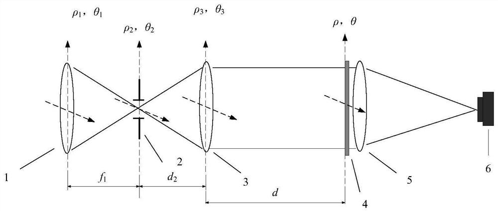
[0045] Such as figure 1As shown, the pupil filter far-field super-resolution imaging system, the system is arranged in sequence along the light incident direction: front optical objective lens 1, field diaphragm 2, collimator lens group 3, pupil filter 4, imaging lens 5 and CCD detector 6, the front-end optical objective lens 1 is used to image the distant scene at the middle image plane of the system, and the field stop 2 is placed on the rear focal plane of the front-end optical objective lens 1, that is, at the middle image plane of the entire system, The front focus of the collimator lens group 3 is at the middle image plane of the system, and the pupil filter 4 is placed at the exit pupil position of the rear end of the system where the front end optical objective lens 1 ...


PUM


Abstract

The pupil filter far-field super-resolution imaging system and pupil filter design method belong to the field of super-resolution imaging technology, in order to solve the problem that the final super-resolution imaging is seriously affected in the existing field diaphragm scanning far-field super-resolution imaging system For quality issues, the system is set up in sequence along the light incident direction: front-end optical objective lens, field diaphragm, collimator lens group, pupil filter, imaging lens and CCD detector, and the front-end optical objective lens is used to image distant scenes At the intermediate image plane of the system, the field diaphragm is placed on the rear focal plane of the front optical objective lens, that is, at the intermediate image plane of the entire system, the front focus of the collimator group is at the intermediate image plane of the system, and the pupil filter is placed on the front optical The exit pupil position of the rear end of the system combined with the objective lens and the collimating lens group, and the position and size of the effective aperture of the pupil filter coincide with the exit pupil surface, the imaging lens will perform secondary imaging on the light passing through the pupil filter, and the CCD detector The target plane coincides with the secondary imaging plane.

Description

technical field [0001] The invention belongs to the technical field of super-resolution imaging, and in particular relates to a pupil filter far-field super-resolution imaging system and a pupil filter design method. Background technique [0002] Diffraction effect is a basic property of light waves, so the resolution of traditional optical systems is limited by the system numerical aperture NA and operating wavelength λ. How to break through the optical diffraction limit and obtain super-resolution, so as to obtain finer object-space scene details is one of the constant pursuits in the optical field. At present, placing a wavefront modulation module at the pupil of the system, that is, pupil filtering, is considered to be a promising technology to achieve far-field super-resolution. [0003] The Chinese patent application number is: "201610517791.4", and the patent name is "a broadband far-field super-resolution imaging device". The technical solution is: a broadband far-...

Claims


Application Information

Patent Timeline
Patent Type & Authority Patents(China)
IPC IPC(8): G02B27/58G02B27/00G02B27/46
CPCG02B27/58G02B27/0012G02B27/46
Inventor 王超刘壮史浩东付强李英超魏明
Owner CHANGCHUN UNIV OF SCI & TECH
Why Eureka
Try Eureka