
System and method for placing and taking wafer on vacuum chuck by Bernoulli manipulator

A vacuum chuck and manipulator technology, applied in piping systems, mechanical equipment, electrical components, etc., can solve the problems of reducing the success rate of Bernoulli manipulators, increasing the wafer fragmentation rate, and failing to absorb wafers. It is not easy to achieve. The effect of crushing, reducing fragmentation rate and reducing warpage

Pending Publication Date: 2020-04-24
BEIJING U PRECISION TECH
View PDF0 Cites 0 Cited by
  • Summary
  • Abstract
  • Description
  • Claims
  • Application Information

AI Technical Summary

Problems solved by technology

When the Bernoulli manipulator absorbs the wafer, one situation is that the adsorption force of the Bernoulli manipulator is less than the surface tension, which causes the Bernoulli manipulator to fail to pick up the wafer.
The second situation is that the adsorption force of the Bernoulli manipulator is slightly greater than the surface tension. The Bernoulli manipulator can take the wafer away, but the warpage of the wafer will increase, which will affect the performance of the wafer itself. This situation is easy What happened was that although the Bernoulli manipulator removed the wafer from the chuck, due to the effect of surface tension, the position of the wafer on the Bernoulli manipulator shifted, which caused the Bernoulli manipulator to alarm and reduced the Bernoulli manipulator. The success rate of taking films with a robotic arm
The third situation is that the adsorption force of the Bernoulli manipulator is much greater than the surface tension, so that the wafer fragmentation rate will increase significantly during the process of picking up the wafer

Method used


Image

  • System and method for placing and taking wafer on vacuum chuck by Bernoulli manipulator
  • System and method for placing and taking wafer on vacuum chuck by Bernoulli manipulator

Examples


Embodiment Construction

[0037] In order to make the technical problems, technical solutions and advantages to be solved by the present invention clearer, the following will describe in detail with reference to the drawings and specific embodiments.

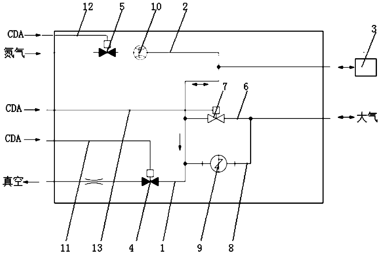
[0038] In one aspect, an embodiment of the present invention provides a system for a Bernoulli manipulator to pick and place a wafer on a vacuum chuck, which includes a Bernoulli manipulator, a vacuum chuck and an air circuit. Such as figure 1 As shown, the gas path includes a first pipeline 1 and a second pipeline 2, wherein:

[0039] One end of the first pipeline 1 is connected to the vacuum, and the other end is connected to the vacuum chuck 3 , and a first pneumatic valve 4 is arranged on the first pipeline 1 .

[0040] The connection of the first pipeline to vacuum in the present invention means that the first pipeline is connected to various devices or systems capable of providing vacuum, and the present invention does not limit the structural for...


PUM


Abstract

The invention discloses a system and a method for placing and taking a wafer on a vacuum chuck by a Bernoulli manipulator, which belong to the field of semiconductor wafer processing. The system comprises the Bernoulli manipulator, a vacuum chuck and a gas circuit. The gas circuit comprises a first pipeline and a second pipeline. One end of the first pipeline is connected with vacuum, and the other end of the first pipeline is connected with the vacuum chuck. A first pneumatic valve is arranged on the first pipeline. One end of the second pipeline is connected with nitrogen, and the other endof the second pipeline is connected with the vacuum chuck. A second pneumatic valve is arranged on the second pipeline. A first bypass pipeline is arranged on the first pipeline. One end of the firstbypass pipeline is connected with the atmosphere, and the other end of the first bypass pipeline is connected with the first pipeline between the first pneumatic valve and the vacuum chuck. A third pneumatic valve is arranged on the first bypass pipeline. According to the invention, the wafer placing and taking position is accurate; the warping degree of the wafer is reduced; and the wafer fragmentation rate is reduced.

Description

technical field [0001] The invention relates to the field of semiconductor wafer processing, in particular to a system and method for a Bernoulli manipulator to pick and place wafers on a vacuum chuck. Background technique [0002] Wafer refers to the silicon wafer used in the production of silicon semiconductor integrated circuits. It is the basic material for manufacturing semiconductor chips. Because of its circular shape, it is called a wafer. [0003] Bernoulli's principle can be vividly expressed as: In water or air flow, if the speed is small, the pressure will be high, and if the speed is high, the pressure will be small. The Bernoulli manipulator (suction cup) is exactly the manipulator that utilizes Bernoulli's principle, and the gas (such as the inert gas such as nitrogen) that ejects in the jet mouth of manipulator meets the surface of disc (for example upper surface, also can be lower surface of course, After the above surface is described as an example), the g...

Claims


Application Information

Patent Timeline
IPC IPC(8): H01L21/683B25B11/00F17D1/04F17D3/01
CPCB25B11/005F17D1/04F17D3/01H01L21/6838
Inventor 刘效岩张程鹏王建程闻兴
Owner BEIJING U PRECISION TECH
Learn More