Drop ball forming device and oil ammonia column forming device

A molding device and drop ball technology, which is applied in chemical instruments and methods, liquid separation into beads and granulation, physical/chemical process catalysts, etc. Catalyst particle size and other issues, to achieve the effect of rapid replacement

Active Publication Date: 2020-04-28
CHINA PETROLEUM & CHEM CORP +1
View PDF4 Cites 1 Cited by
  • Summary
  • Abstract
  • Description
  • Claims
  • Application Information

AI Technical Summary

Problems solved by technology

[0008] The purpose of the present invention is to provide a drop ball forming device in order to overcome the problems that the ball dropper of the oil ammonia column forming device

Method used


Image

  • Drop ball forming device and oil ammonia column forming device
  • Drop ball forming device and oil ammonia column forming device

Examples


Embodiment approach

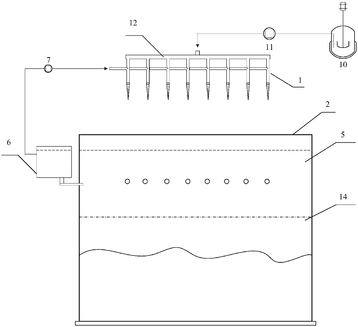
[0052] According to a preferred embodiment of the present invention, the drop ball forming device further includes: a horizontal tube distributor 12, which communicates with the outlet of the slurry tank 10 and the inlet of each slurry feed pipe 3 . The horizontal tube distributor 12 can ensure that the slurry feed volume of each dropper 1 is the same. Specifically, the inlet of the horizontal tube distributor 12 communicates with the outlet of the slurry tank 10, and the outlet of the horizontal tube distributor 12 communicates with the inlet of each slurry feeding pipe 3 respectively.

[0053] According to a specific embodiment of the present invention, a slurry pump 11 is provided on the pipeline connecting the inlet of the horizontal tube distributor 12 and the outlet of the slurry tank 10.

[0054] According to a specific embodiment of the present invention, the protective oil feed pipe 4 of each ball dropper 1 is connected in parallel with the pulse pump 7.

[0055] The drop ...

Embodiment 1

[0063] It is explained that the drop ball forming device and the oil ammonia column forming device provided by the present invention produce alumina carrier pellets.

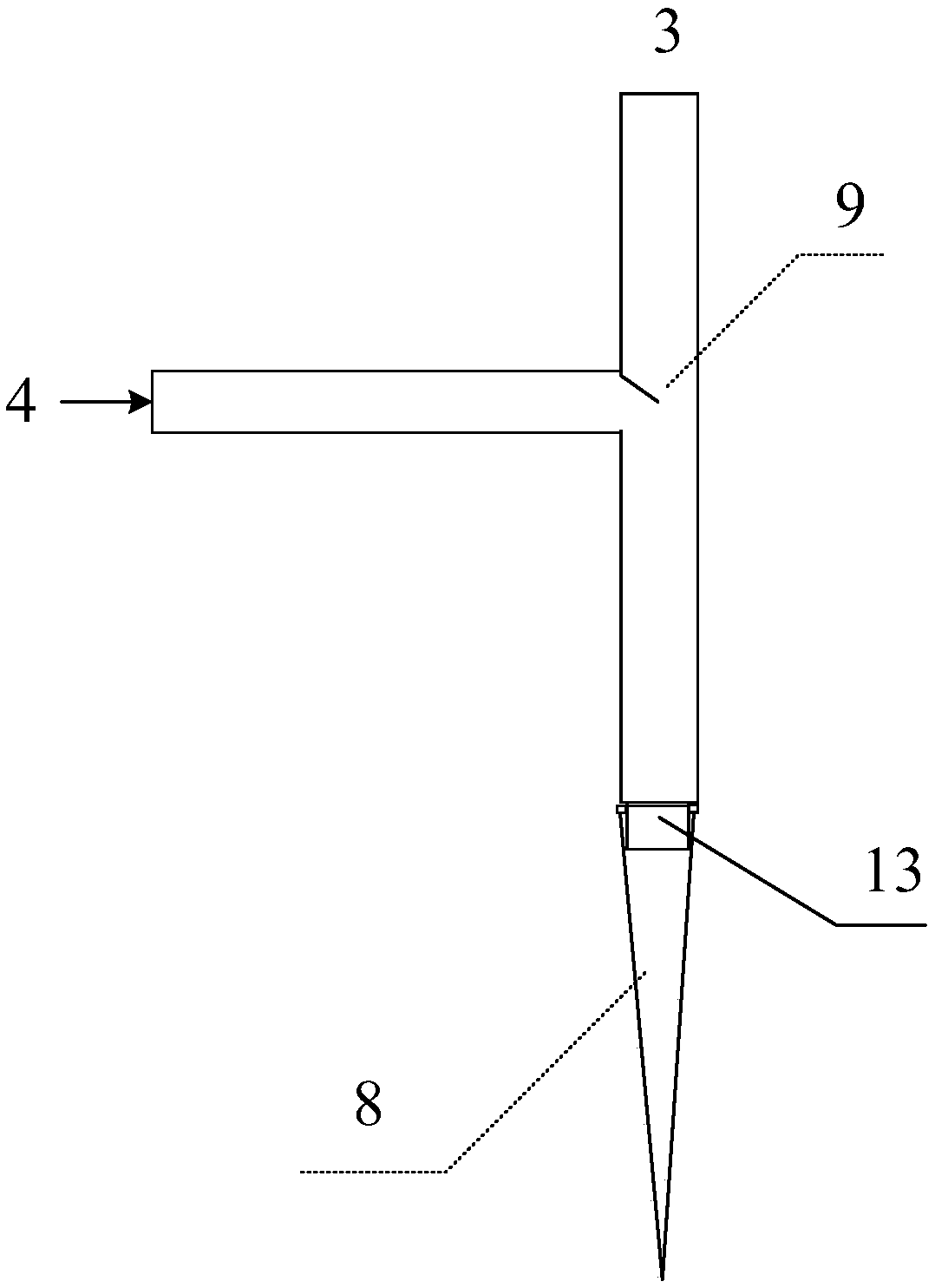
[0064] Such as figure 2 As shown, the dripping device includes 6 drippers 1 arranged side by side in parallel, the drippers 1 such as figure 1 As shown, it includes: a slurry feed pipe 3, a protective oil feed pipe 4 and a dripper 8; the slurry feed pipe 3 is set up vertically, and the protective oil feed pipe 4 is set horizontally. The inner diameter of the slurry feed pipe 3 is 5mm , The inner diameter of the protective oil feed pipe 4 is 5mm; the intersection of the slurry feed pipe 3 and the upper wall of the protective oil feed pipe 4 is provided with a guide plate 9, and one end (arc) of the guide plate 9 is welded to the slurry feed At the junction of the pipe 3 and the protective oil feed pipe 4, the width of the guide plate 9 is the same as the diameter of the slurry feed pipe 3. The guide plate 9 is arra...

Embodiment 2

[0072] It is explained that the drop ball forming device and the oil ammonia column forming device provided by the present invention produce molecular sieve-alumina pellets.

[0073] According to Example 1, the difference is that the slurry containing oxide particles: use HY molecular sieve and aluminum sol as raw materials to continuously produce HY-alumina pellets. The solid content of HY in the raw materials is 35% by weight, and the solid content of aluminum sol is 30% by weight, the molecular sieve and alumina sol are mixed at a mass ratio of 1:1 to form a slurry, and the solid content of the slurry is 25% by weight to prepare HY-alumina pellets (alumina: HY weight ratio is 1:1) .

[0074] During the whole dripping process, the dripper did not appear to stick, and there were no sticking small balls. The prepared HY-alumina pellets have good sphericity and uniform particle size, the particle size of the pellets is about 1.6 mm, the bulk density is 0.6 g / ml, and the crushing st...


PUM

PropertyMeasurementUnit
Inner diameteraaaaaaaaaa
Particle sizeaaaaaaaaaa
Bulk densityaaaaaaaaaa

Abstract

The invention relates to the field of oil ammonia column forming, and discloses a drop ball forming device and an oil ammonia column forming device. The drop ball forming device comprises a pluralityof drop ball devices (1), wherein the drop ball device (1) comprises a slurry feeding pipe (3), a protective oil feeding pipe (4) and a dripper (8), the slurry feeding pipe (3) is communicated with aslurry tank (10) through a pipeline, the slurry tank (10) is used for providing slurry containing oxide particles for the slurry feeding pipe (3), the protective oil feeding pipe (4) is communicated with a protective oil buffer tank (6), a pulse pump (7) is arranged on a communication pipeline, and the included angle between the arrangement direction of the slurry feeding pipe (3) and the arrangement direction of the protective oil feeding pipe (4) is 10-90 DEG. The device provided by the invention overcomes the defects of slurry blockage and adhesion, can realize accurate control of the droplet size, and can produce pellet catalysts with different particle size requirements.

Description

Technical field [0001] The invention relates to the field of oil ammonia column forming, in particular to a drop ball forming device and an oil ammonia column forming device. Background technique [0002] The oil-ammonia column forming method is a common method for preparing alumina, silica, silicon-alumina and other pellets. In this method, the sol (such as aluminum sol, silica sol, etc.) is dropped into the oil ammonia column, so that the sol forms a ball in the oil phase of the upper layer of the oil ammonia column, and gels in the lower layer of ammonia water. After the gelled particles are aged, they are dried and calcined to obtain spherical solid particles. The pellets prepared by this method have uniform structure, low abrasion and high strength, and are widely used as fixed bed and moving bed catalysts, catalyst carriers and adsorbents. [0003] Industrial catalysts have different shapes and sizes according to the requirements of process operations. Therefore, the moldin...

Claims


Application Information

Patent Timeline
IPC IPC(8): B01J2/06B01J35/08B01J37/00
CPCB01J2/06B01J37/0072B01J35/08
Inventor 张翊韩颖高秀枝胡立峰何金龙田志鸿李学锋刘亚林
Owner CHINA PETROLEUM & CHEM CORP
Why Eureka
Try Eureka