Dust collection polar plate for plasma organic waste gas treatment

An organic waste gas and plasma technology, applied in electrode structure, electrostatic separation, electrode cleaning, etc., can solve the problems of poor particle treatment effect, detachment from the attraction of the electrode plate, reducing the stability of plasma treatment equipment, etc., and achieves high treatment efficiency. Enhanced effect

Active Publication Date: 2020-04-28
康森(杭州)环保有限公司
View PDF8 Cites 0 Cited by
  • Summary
  • Abstract
  • Description
  • Claims
  • Application Information

AI Technical Summary

Problems solved by technology

[0003] 1. The existing patent No. CN207091541U proposes an electrolytic cleaning plate device with an anti-collision block, which reduces the influence of vibration through the setting of the anti-collision block, but it does not solve the problem after the plate is connected to the vibration device, because the vibration frequency and The amplitude is relatively high, which will inevitably generate certain noise, and the shaking device is connected to the plate and the plasma processing equipment, which will vibrate the plasma processing equipment and reduce the stability of the plasma processing equipment.
[0004] 2. The existing patent No. CN102909134B proposes a mobile plate electrostatic precipitator, which removes the particles on the plate by means of a rotating brush, but it does not solve the problem that the particles will fall away from the attraction of the plate. If there is no high sealing A permanent receiving device is used to accept the particles that have been shaken off, and some of them will be re-integrated into the rising exhaust gas, resulting in poor particle treatment in the exhaust gas.
[0005] In addition, the existing plate still has the problem that the efficiency of particles being shaken and dropped is limited by the frequency and amplitude of the shake, and no matter how high the frequency and amplitude are, it will take a certain amount of time for the shake to fall from the plate smoothly, and the exhaust gas Medium particle treatment efficiency is low

Method used


Image

  • Dust collection polar plate for plasma organic waste gas treatment
  • Dust collection polar plate for plasma organic waste gas treatment
  • Dust collection polar plate for plasma organic waste gas treatment

Examples


Embodiment 1

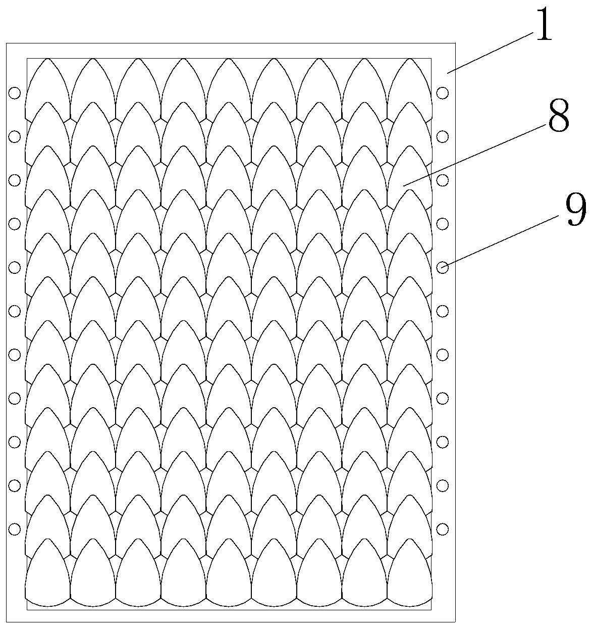
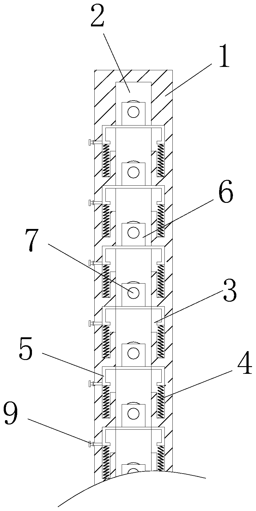
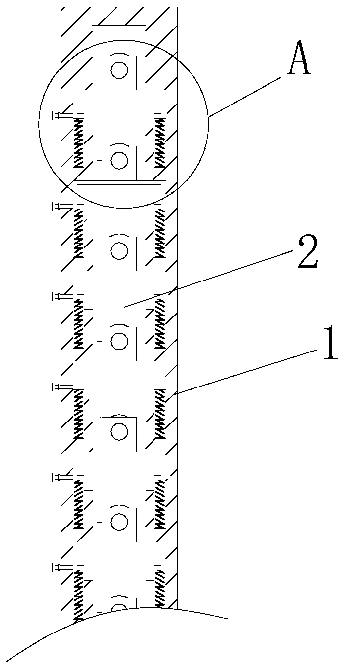
[0032] Example 1: Please refer to Figure 1-2, The present invention proposes a dust collector plate for plasma organic waste gas treatment, comprising a frame body 1, the frame body 1 is a rectangular body with a hollow center, and the inner walls of the left and right sides of the frame body 1 are provided with sliding holes 2. The sliding holes 2 is a rectangular hole, the front and rear inner walls of the two sliding holes 2 are provided with thirteen groups of chutes 3, and the number of each group of chutes 3 is two and located on the front and rear inner walls of the sliding holes 2, respectively, and the chutes 3 are inverted L. The inner wall of the bottom surface of the chute 3 is fixedly connected with a return spring 4, and the unfixed end of the return spring 4 in each set of chute 3 is fixedly connected with a movable plate 5. The shape of the movable plate 5 is a C-shaped body, and the movable plate 5 The top surface is provided with a rectangular protrusion 6, ...

Embodiment 2

[0033] Example 2: Please refer to Figure 3-4 , On the basis of the first embodiment, the bottom surface of the movable plate 5 is fixedly connected with a frosted plate 10, the frosted plate 10 and the rectangular protrusion 6 are staggered left and right, and the frosted plate 10 is attached to the front side of the circular rod 7 under the movable plate 5, and the frosted The plate 10 has two functions. First, it is attached to the round rods 7 in the next row, so as to limit the rotation of the round rods 7. When the electrode sheet 8 is pushed by the rising exhaust gas and its own weight changes, it can also keep the electrode sheet 8. Secondly, when the electrode sheet 8 is lowered due to the accumulation of particles, the matte plate 10 is attached to the round rod 7 to drive the electrode sheet 8 in the next row to be in an unfolded state, so that the concave surface of the electrode sheet 8 is the same as the one in the previous row. The positions of the electrode she...

Embodiment 3

[0034] Example 3: Please refer to Figure 5 , On the basis of the first embodiment, the electrode sheet 8 is in the shape of scales, and the scale-shaped electrode sheet 8 can reduce the frictional force generated when contacting with the exhaust gas, thereby reducing the degree of friction on the electrode sheet 8 after being in contact with the exhaust gas for a long time. The back side of the sheet 8 is concave, the back side of the electrode sheet 8 is fixedly connected with an insulating pad 11, the shape and size of the insulating pad 11 are adapted to the electrode sheet 8, and the back side of the insulating pad 11 is fixedly connected with a slideway plate 12. The shape of the slide plate 12 is a fan-shaped body, and the bottom end of the sliding plate and the insulating pad 11 have an included angle of 30 degrees. Provides acceleration, thereby accelerating particle removal.


PUM


Abstract

The invention relates to the technical field of waste gas treatment, and discloses a dust collection polar plate for plasma organic waste gas treatment. The dust collection polar plate comprises a frame body, wherein the inner walls of the frame body are provided with sliding holes; sliding grooves are formed in the inner walls of the sliding holes; reset springs are fixedly connected to the innerwalls of the sliding grooves; the reset springs are fixedly connected with a movable plate; a rectangular bulge is arranged on the top surface of the movable plate; a circular hole is formed in the rectangular bulge; a round rod is sleeved in the round hole; and electrode plates are laid on the outer walls of each round rod. Compared with a mode of removing particles by shaking, through the arrangement of the structures such as the electrode plates, no large-amplitude and high-frequency movement is generated in the particle removing process, no noise is generated, and the stability of the plasma treatment equipment is not reduced. In addition, the particles can be automatically separated from the electrode plates and do not stay on the electrode plates after the electrode plates lose electric power circulation, the particle treatment efficiency is high, the falling particles can be covered by the next row of electrode plates, direct contact with rising waste gas is blocked, and the treatment effect of the particles in the waste gas is enhanced.

Description

technical field [0001] The invention relates to the technical field of waste gas treatment, in particular to a dust collecting electrode plate for plasma organic waste gas treatment. Background technique [0002] The method of plasma treatment of organic waste gas is to use high-voltage discharge to decompose the components in the exhaust gas. When processing the exhaust gas with flue gas, the high-voltage discharge will attach negative electrons to the particles in the exhaust gas, and these particles with negative electrons will be negatively charged. Actively attracted by the plate with positive voltage and adsorbed on the plate. When the existing dust collector plate for plasma organic waste gas treatment is used, the particles adsorbed on the plate are usually removed by connecting a shaking device, but this method has the following problems: [0003] 1. The existing patent number CN207091541U proposes an electrolytic cleaning plate device with anti-collision block, wh...

Claims


Application Information

Patent Timeline
Patent Type & Authority Applications(China)
IPC IPC(8): B03C3/47B03C3/76B03C3/88
CPCB03C3/47B03C3/76B03C3/88Y02A50/20
Inventor 吴文娟
Owner 康森(杭州)环保有限公司
Why Eureka
Try Eureka