
Visualization system for welding robot and using method of visualization system

A welding robot and welding system technology, applied in the field of visualization systems, can solve the problems of high safety hazards for operators, short effective working hours, and large dimensions, and achieve simple structural layout, friendly and uniform, reduced labor intensity and The effect of auxiliary time

Inactive Publication Date: 2020-04-28
CHONGQING TIEMA IND GRP
View PDF13 Cites 0 Cited by
  • Summary
  • Abstract
  • Description
  • Claims
  • Application Information

AI Technical Summary

Problems solved by technology

In addition, due to the large size of the car body, there are many components that form the shell, and there is a certain accumulation of errors. The position of the welding bead of each car body is offset. All car bodies must repeat the teaching of the front car body. Action
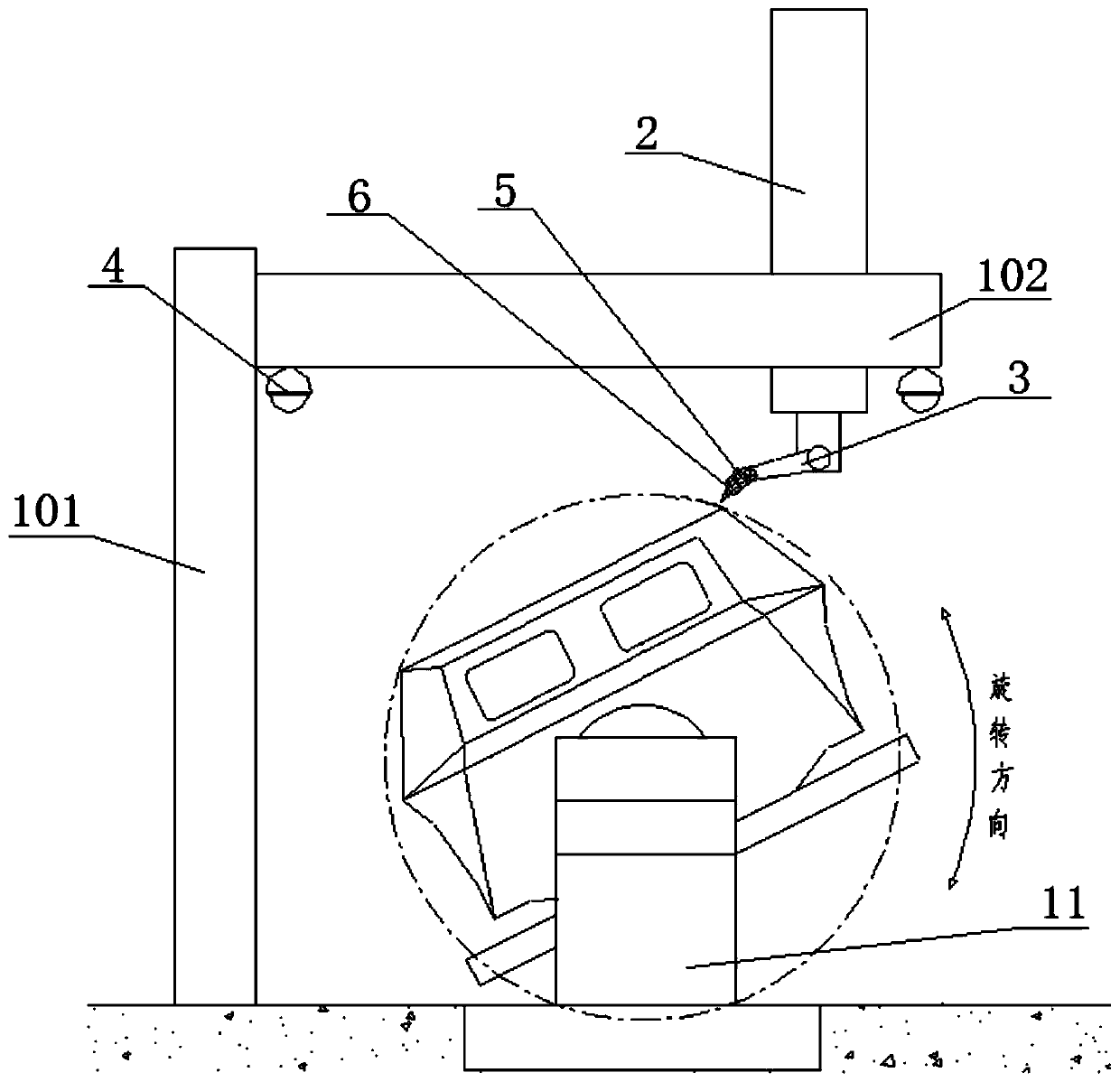
At present, when welding robots in the same industry are welding armored vehicle shells, due to the large number of welds and the large size of the car body, the operator cannot effectively complete the search for welds on the remote platform or stairs. To observe the weld bead during welding, it is necessary to climb onto the car body for corresponding operations, but the car body rotates during the teaching operation, and there are high safety hazards for the operators. The auxiliary time is long, the labor intensity is high, and the effective working time is short

Method used


Image

  • Visualization system for welding robot and using method of visualization system
  • Visualization system for welding robot and using method of visualization system
  • Visualization system for welding robot and using method of visualization system

Examples


Embodiment 1

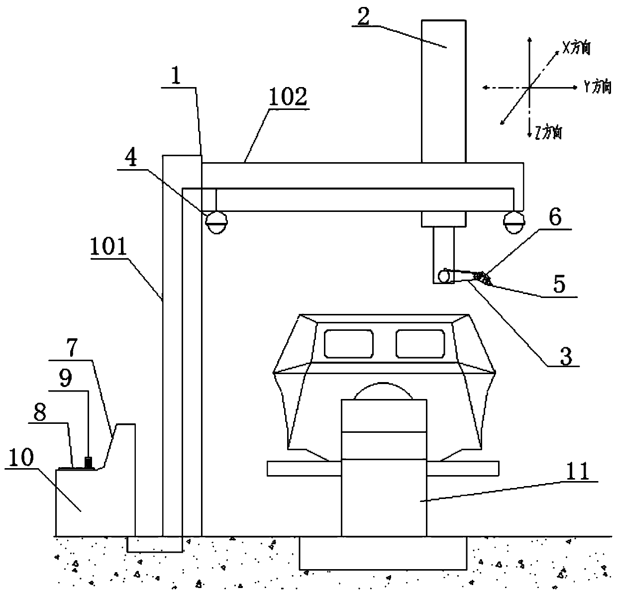
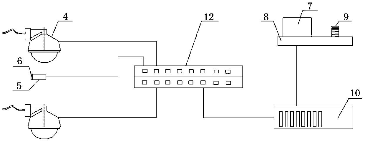
[0033] This embodiment discloses a visualization system for a welding robot, including a welding system, a vision system, a control system and a drive system.

[0034] see figure 1 , the welding system includes a frame 1, a welding arm 2 and a welding torch 3.

[0035] The frame 1 includes beams 101 and support columns 102 . The support column 102 is installed vertically on the ground. The beam 101 is welded and fixed on the upper end of the support column 102 and is perpendicular to the support column 102 . The crossbeam 101 is equipped with a longitudinal guide rail X, a transverse guide rail Y and a vertical guide rail Z. A three-dimensional coordinate system oxyz is established on the crossbeam 101. The longitudinal guide rail X is located in the x-axis direction, and the transverse guide rail Y is located in the y-axis direction. The guide rail Z is located in the z-axis direction.

[0036] The welding arm 2 is vertically installed on the beam 101 . The welding arm 2...

Embodiment 2

[0045] This embodiment provides a relatively basic implementation, including a welding system, a vision system, a control system and a drive system.

[0046] see figure 1 , the welding system includes a frame 1, a welding arm 2 and a welding torch 3.

[0047] The frame 1 includes beams 101 and support columns 102 . The support column 102 is installed vertically on the ground. The beam 101 is welded and fixed on the upper end of the support column 102 and is perpendicular to the support column 102 . The welding arm 2 is vertically installed on the beam 101 .

[0048] The welding torch 3 is mounted on the lower end of the welding arm 2 . The welding arm 2 has a human-like arm motion simulation function, and through its built-in joint mechanism, the welding torch 3 can be made to move in any angle and direction.

[0049] The vision system includes two spherical cameras 4 and a bullet camera 5. In this embodiment, both the spherical camera 4 and the bullet camera 5 are high-d...

Embodiment 3

[0056] The main structure of this embodiment is the same as that of Embodiment 2. Further, the longitudinal guide rail X, the horizontal guide rail Y and the vertical guide rail Z are installed on the beam 101, and a three-dimensional coordinate system oxyz is established on the beam 101, and the longitudinal guide rail X is located in the x-axis direction. , the horizontal guide rail Y is located in the y-axis direction, and the vertical guide rail Z is located in the z-axis direction.

[0057] The welding arm 2 is respectively equipped with driving devices moving along the directions of the longitudinal guide rail X, the transverse guide rail Y and the vertical guide rail Z, so that the welding arm 2 can move in the directions of x, y and z.


PUM


Abstract

The invention discloses a visualization system for a welding robot and a using method of the visualization system. The system comprises a welding system, a visual system, a control system and a driving system, wherein the welding system comprises a rack, a welding arm and a welding gun, the rack comprises a cross beam and a supporting column, the visual system comprises two spherical cameras and agun type camera, the control system comprises a terminal, the driving system comprises a positioner, when in use, a vehicle body to be welded is fastened on the positioner, the spherical cameras collect digital video signals of the area of the vehicle body to be welded and output the signals to the terminal, the gun type camera collects a digital video signal of the welding bead area and outputsthe signal to the terminal, and through parallel cooperation of the terminal and a demonstrator, searching of a welding bead of the to-be-welded vehicle body, observation of welding seam quality and the like are completed. According to the system and the method, the problem that the high potential safety hazard exists due to the fact that in the prior art, a worker must climb to the vehicle body for short-distance operation when searching and observing the welding bead is solved, and the labor intensity and the auxiliary time are obviously reduced.

Description

technical field [0001] The invention relates to the field of welding robots, in particular to a visualization system for welding robots and a method for using the same. Background technique [0002] The working principle of the welding robot welding the armored car body: After the armored car body is fixed on the positioner of the welding robot, the operator controls the arm movement of the robot and the turning of the positioner through the teaching pendant, and welds the welds to be welded one by one. Search, and complete the compilation and determination of the NC program in the process, and finally carry out welding. In addition, due to the large size of the car body, there are many components that form the shell, and there is a certain accumulation of errors. The position of the welding bead of each car body is offset. All car bodies must repeat the teaching of the front car body. action. At present, when welding robots in the same industry are welding armored vehicle...

Claims


Application Information

Patent Timeline
Patent Type & Authority Applications(China)
IPC IPC(8): B23K37/00B23K37/02B23K37/047
CPCB23K37/00B23K37/0252B23K37/047
Inventor 朱成刚廖周文韩世伟王静吴旭范星星郑晶
Owner CHONGQING TIEMA IND GRP
Learn More