Glass kiln upper and lower layer electrode propelling device and method

A glass furnace and propulsion device technology, applied in glass furnace equipment, glass manufacturing equipment, furnaces, etc., can solve problems such as unreachable, large propulsion error, and inability to meet the melting requirements of furnace glass liquid, so as to avoid dislocation Effect

Active Publication Date: 2020-04-28
IRICO DISPLAY DEVICES
View PDF9 Cites 4 Cited by
  • Summary
  • Abstract
  • Description
  • Claims
  • Application Information

AI Technical Summary

Problems solved by technology

[0003] During the heating process of electrofusion, due to the chemical purity of the electrode, metallographic structure, surface characteristics, initial protective layer, mechanical stress in the manufacturing process, etc., as well as the solute temperature, current density, and chemical composition of the glass, etc. The combined effect causes erosion of the furnace electrodes, and the Joule heat generated becomes smaller due to the increase of the electrode spacing, which cannot meet the melting requirements of the furnace glass liquid. It is necessary to push the electrodes into the furnace to meet the specified requirements for the electrode spacing of the pool furnace.
At present, the kiln electrodes are pushed in layers by cross-rotating six screws. The process of pushing the kiln electrodes by this method is cumbersome, and at the same time, it is easy to produce large propulsion errors. The upper water cooling plate and the lower water cooling plate divide the kiln electrodes into upper and lower parts. layer, during the advancement of the kiln electrode, due to the advancement of the upper and lower layers, the advancement of the upper electrode and the lower electrode is inconsistent and dislocation occurs, which will lead to the failure to achieve the expected advancement effect, and also greatly affect the service life of the electrode

Method used


Image

  • Glass kiln upper and lower layer electrode propelling device and method
  • Glass kiln upper and lower layer electrode propelling device and method

Examples


Embodiment Construction

[0034] The present invention will be further described in detail below in conjunction with specific embodiments, which are explanations of the present invention rather than limitations.

[0035] The orientation words used in the examples such as "up, down, left, right, top, bottom" usually refer to the corresponding structure of the upper and lower electrode propulsion devices of the glass furnace under the use state of "up, down, left, right, top, bottom "; "front and rear" refer to the positional relationship relative to the glass furnace; "advancing direction" refers to the direction in which the furnace electrode is pushed from the outside to the inside relative to the glass furnace.

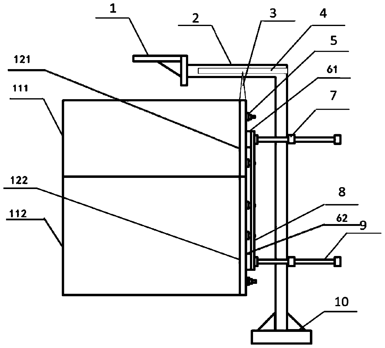
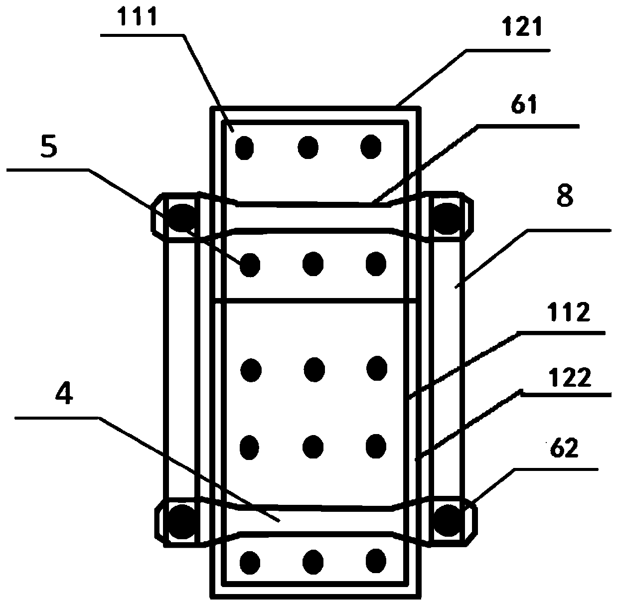
[0036] The invention relates to a propelling device and method for upper and lower electrodes of a glass furnace. Such as figure 1 with figure 2 As shown, the upper water cooling plate 121 and the lower water cooling plate 122 divide the kiln electrodes into upper and lower layers, the re...


PUM


Abstract

The invention discloses a glass kiln upper and lower layer electrode propelling device and method. The device comprises a pressing plate connecting frame and a propelling screw rod, wherein an upper water cooling plate is fixedly connected to the rear end of the upper-layer electrode in the propelling direction, and an upper electrode pressing plate is fixedly connected to the rear end of the upper water cooling plate in the propelling direction; a lower water cooling plate is fixedly connected to the rear end of the lower-layer electrode in the propelling direction, and a lower electrode pressing plate is fixedly connected to the rear end of the lower water cooling plate in the propelling direction; the two ends of the pressing plate connecting frame are fixedly connected with the upper electrode pressing plate and the lower electrode pressing plate respectively; the propelling screw rod is in threaded connection with a supporting frame and abuts against the upper electrode pressing plate and / or the lower electrode pressing plate. According to the method, through step-by-step propelling, the propelling accuracy of kiln electrodes is guaranteed, propelling errors are reduced, largeerrors caused by one-time propelling are prevented, and propelling errors in the propelling process of the upper-layer electrode and the lower-layer electrode are reduced.

Description

technical field [0001] The invention relates to the technical field of substrate glass manufacturing, in particular to an upper and lower layer electrode propulsion device and method of a glass kiln furnace. Background technique [0002] In the manufacturing process of glass substrates, the kiln pool is the key equipment for melting glass batch materials to form glass liquid. When making new high-performance glass (such as: liquid crystal basic glass, screen protection glass, LTPS glass), the furnace in the production line adopts a hot-top electric melting or electric-assisted melting furnace, and the current is introduced into the glass liquid through the electrode. The molten glass between the two electrodes generates Joule heat under the action of alternating current, so as to achieve the purpose of fully melting the glass batch material, preventing the lower layer of the molten glass from staying at a lower temperature for a long time and adjusting the temperature. [0...

Claims


Application Information

Patent Timeline
Patent Type & Authority Applications(China)
IPC IPC(8): C03B5/03C03B5/16
CPCC03B5/03C03B5/16Y02P40/57
Inventor 李淼俞超张峰李豹杨国洪
Owner IRICO DISPLAY DEVICES
Why Eureka
Try Eureka