Novel well cementation truck

A new type of cementing technology, applied in the field of new cementing vehicles, can solve the problems of complex operation, unsatisfactory, time-consuming, etc., and achieve the effect of flexible and efficient movement, optimized space layout, and simple and convenient operation

Pending Publication Date: 2020-04-28
YANTAI JEREH PETROLEUM EQUIP & TECH CO LTD
View PDF0 Cites 114 Cited by
  • Summary
  • Abstract
  • Description
  • Claims
  • Application Information

AI Technical Summary

Problems solved by technology

Directly supply ash to the cementing vehicle through the vertical ash tank, which cannot guarantee the stability of ash supply speed and flow rate, and affects the mixing quality of the cementing vehicle
In order to improve the quality of slurry mixing, ash tanks, air bottles, air compressors and other equipment are usually used to ash by air spraying. However, due to the constraints of the well site scale and transportation conditions, the ash tanks are not available for every well site. standard equipment
At present, in the existing technology, the pressure-stabilizing ash tank has been integrated on the trailer chassis, but this method needs to be equipped with an air bottle and an air compressor separately. The air compressor and the air bottle need another carrier to carry them, and the trailer chassis itself Large size, large footprint, plus the carrier of the air bottle and air compressor, the cementing vehicle occupies a very large space when it is working, which cannot meet the requirements of large operations in small well sites; the chassis itself has no power end, and when moving Additional power is needed to drive the movement, the operation is complex, time-consuming, and cannot meet the requirements of high-efficiency operations

Method used


Image

  • Novel well cementation truck
  • Novel well cementation truck

Examples


Embodiment Construction

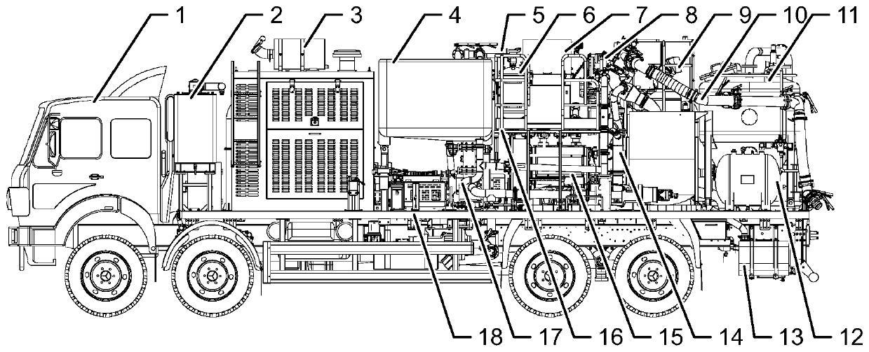
[0018] like figure 1 and figure 2 As shown, a new type of cementing vehicle includes a loading body 1, an electrical system 8, a plunger pump 15, a clean water manifold 17, a mud manifold 14 and a high pressure manifold. The loading body 1 is provided with a beam 18, and the A hydraulic system 2, a power transmission system 3, a metering tank 4, an operating platform 16 and a mixing system 9 are sequentially installed on the beam 18, an air circuit system 5 and an operating system 7 are sequentially installed on the operating platform 16, and the electrical system 8 supplies power to the cementing vehicle, and the plunger pump 15, clean water manifold 17, mud manifold 14 and high pressure manifold are all arranged under the operation platform 16, and the clean water manifold 17 is the The pump 15 and the mixing system 9 provide clean water, the mud manifold 14 provides mud for the plunger pump 15, and the plunger pump 14 injects mud into the well through the high-pressure ma...


PUM


Abstract

The invention discloses a novel well cementation truck, which comprises a loading body, an electrical system, a plunger pump, a clear water manifold, a mud manifold and a high-pressure manifold, wherein the loading body is provided with a cross beam; the cross beam is provided with a hydraulic system, a power transmission system, a metering tank, an operating platform and a mixing system in sequence; the operating platform is provided with a gas path system and an operating system in sequence; the electrical system supplies power to the well cementation truck; the plunger pump, the clear watermanifold, the mud manifold and the high-pressure manifold are all arranged below the operating platform; the clear water manifold supplies water to the plunger pump and the mixing system; the mud manifold provides mud for the plunger pump; the plunger pump injects the mud into a well through the high-pressure manifold; and the well cementation truck also integrates with a steady pressure ash can,an air compressor and an air bottle. The novel well cementation truck has the beneficial effects that a spatial layout is optimized, and the steady pressure ash can, the air compressor and the air bottle are integrated in one well cementation truck. An ash feeding manifold is optimized, so that the steady pressure ash can supplies ashes, and ash supply equipment can be externally connected for supplying ashes. The large-volume air bottle is adopted, and therefore, air can be supplied to other equipment while the requirements of the well cementation truck are met.

Description

technical field [0001] The invention relates to the field of petroleum equipment, in particular to a novel well cementing vehicle. Background technique [0002] With the rapid development of shale gas development, there are frequent cementing operations in ultra-deep wells and complex formations in China, and the requirements for the operation quality of cementing vehicles are getting higher and higher. The speed and flow of ash supply have a direct impact on the mud mixing quality of the cementing truck. Directly supplying ash to the cementing truck through the vertical ash tank cannot guarantee the stability of ash supply speed and flow rate, which will affect the mixing quality of the cementing truck. In order to improve the quality of slurry mixing, ash tanks, air bottles, air compressors and other equipment are usually used to ash by air spraying. However, due to the constraints of the well site scale and transportation conditions, the ash tanks are not available for e...

Claims


Application Information

Patent Timeline
Patent Type & Authority Applications(China)
IPC IPC(8): E21B33/13B60P3/00
CPCB60P3/00E21B33/13
Inventor 王彦峰邹力抚李恩杰吴广福刘仁吴张晔吴文全马灯刚王金李宗良
Owner YANTAI JEREH PETROLEUM EQUIP & TECH CO LTD
Why Eureka
Try Eureka