
Projection screen and processing method thereof

A technology of projection screen and processing method, applied in optics, lenses, instruments, etc., can solve the problems of limited effect of structure improvement and contrast

Active Publication Date: 2020-04-28
APPOTRONICS CORP LTD
View PDF13 Cites 5 Cited by
  • Summary
  • Abstract
  • Description
  • Claims
  • Application Information

AI Technical Summary

Problems solved by technology

[0005] The document with the publication number CN105408777A discloses a circular symmetrical Fresnel structure as shown in Figure 2(c). This invention utilizes the different incident angles of projected light and ambient light to improve contrast. The ambient light G2 passes through the reflective layer The upper reflective surface of the reflective layer is reflected to the ground direction, which does not affect the viewing contrast, but there is still a part of the ambient light G1 as shown in the figure, which will be reflected back into the viewing field through the lower reflective surface of the reflective layer
Therefore, the structure in this invention has limited effect on improving contrast

Method used


Image

  • Projection screen and processing method thereof
  • Projection screen and processing method thereof
  • Projection screen and processing method thereof

Examples


Embodiment Construction

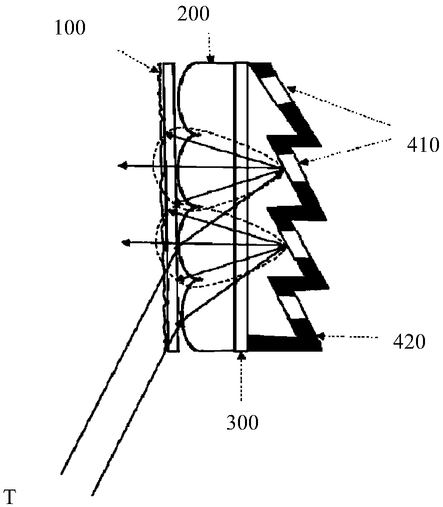
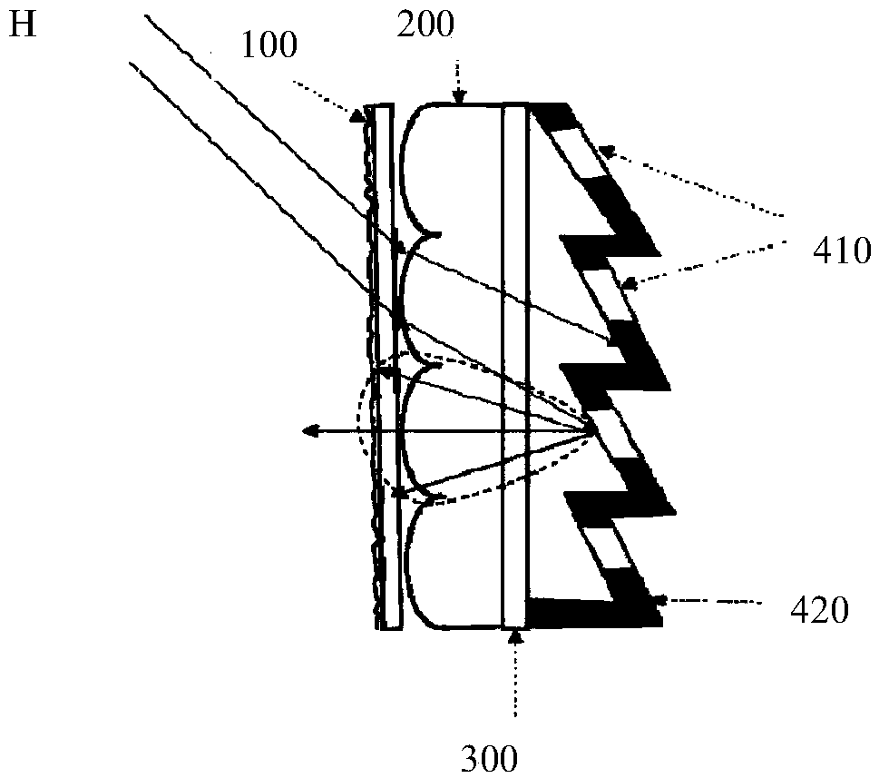
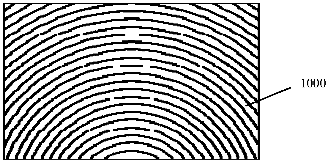
[0039] Fig. 1(a) is a schematic diagram of the light of the projector of the present invention; Fig. 1(b) is a schematic diagram of the ambient light of the present invention; Fig. 1(c) is a schematic diagram of the appearance of the projection screen of the present invention. Such as Figure 1(a) to Figure 1(c) It can be seen that the present invention provides a projection screen 1000, which sequentially includes a diffusion layer 100, a microlens array 200, and a substrate 300 from the incident side of the projection light T, and the inside of the substrate 300 is provided with a Fresnel microstructure 400, and Part of the surface of the Fresnel microstructure 400 is provided with a reflective layer 410 , and the rest of the surface of the Fresnel microstructure is a light-absorbing layer 420 . The microlens array 200 is used to focus the projected light T on the reflective layer 410 , and the reflective layer 410 is used to reflect the projected light T back to the field o...


PUM

PropertyMeasurementUnit
Pitchaaaaaaaaaa

Abstract

The invention provides a projection screen and a processing method thereof. The projection screen comprises a diffusion layer, a micro-lens array and a base material sequentially distributed from a projection light incident side; a Fresnel microstructure is arranged on the inner side of the base material; a reflecting layer is arranged on a part of the surface of the Fresnel microstructure, and alight absorbing layer is arranged on the other part of the surface of the Fresnel microstructure; the micro-lens array is used for focusing projection light on the reflecting layer; the reflecting layer is used for reflecting the projection light back to an audience view field; and most of ambient light is absorbed by the light absorbing layer. According to the projection screen and the processingmethod thereof of the invention, the structure and the size of the micro-lens array are properly set, so that the projection light only enters the reflecting layer of the micro-structure, and most ofthe ambient light is absorbed by the light absorbing layer, and therefore, the light utilization rate and ambient light resistance of the screen are improved; the reflectivity of the screen is reduced, while, the reflectivity of the projector is not reduced. The reflecting screen has high gain and high contrast; the screen is suitable for an ultra-short-focus projector; and a better visual effectof the screen can be ensured.

Description

technical field [0001] The invention relates to a projection screen and a processing method thereof. Background technique [0002] The screen is an important factor affecting the projection display system, which has a great influence on the image quality of the projection display, and the contrast of the screen is a parameter to evaluate the quality of a screen. The contrast of the picture reflected by the screen is affected by the ambient light and is much lower than the contrast of the projector itself. Because the general projector screen can reflect both the light of the projector and the light of the ambient light. [0003] In order to improve the screen contrast in the case of ambient light, the current anti-environmental light projection screen is a wire grid screen disclosed in the document CN1670618A, its structure is shown in Figure 2 (a), the microstructure The unit is composed of upper and lower slopes. The surface of the upper slope is coated with a layer of b...

Claims


Application Information

Patent Timeline
IPC IPC(8): G03B21/602G02B3/00G02B3/08
CPCG03B21/602G02B3/0012G02B3/08G03B21/60G02B5/1895G02B3/0056G02B5/0242G02B5/1861G02B5/003G02B5/1857G02B1/04G02B5/22
Inventor 王霖孙微王杰胡飞李屹
Owner APPOTRONICS CORP LTD
Learn More