
Silicon carbide trench MOSFET device and manufacturing method thereof

A technology of silicon carbide trenches and manufacturing methods, which is applied in semiconductor/solid-state device manufacturing, semiconductor devices, electrical components, etc., and can solve problems such as unfavorable device conduction characteristics, gate dielectric layer breakdown, and high device on-resistance

Inactive Publication Date: 2020-04-28
SHENZHEN INST OF WIDE BANDGAP SEMICON
View PDF5 Cites 4 Cited by
  • Summary
  • Abstract
  • Description
  • Claims
  • Application Information

AI Technical Summary

Problems solved by technology

[0004] Trench MOSFETs mainly face two problems: first, in the on state, the channel carrier mobility is low, which causes a high on-resistance of the device; second, in the blocking state, the trench oxide, Especially the electric field in the gate dielectric layer near the bottom corner of the trench is too large, which leads to premature breakdown of the gate dielectric layer
Usually, methods such as introducing a P-type shielding layer are used to alleviate the electric field of the gate dielectric layer. However, this method will introduce additional on-resistance, which is not conducive to the improvement of device conduction characteristics.

Method used


Image

  • Silicon carbide trench MOSFET device and manufacturing method thereof
  • Silicon carbide trench MOSFET device and manufacturing method thereof
  • Silicon carbide trench MOSFET device and manufacturing method thereof

Examples


Embodiment Construction

[0048] In order to make the object, technical solution and advantages of the present invention clearer, the present invention will be further described in detail below in conjunction with specific embodiments and with reference to the accompanying drawings.

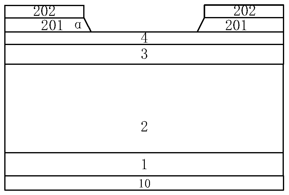
[0049] One aspect of the embodiments of the present invention provides a silicon carbide trench MOSFET device structure. The device structure of the silicon carbide trench MOSFET device includes an N+ type silicon carbide substrate 1, above which is an N-type drift Region 2, P-type base region 3, N+ type source region 4. There is a drain electrode 10 at the bottom of the N+ type substrate 1, and an inverted trapezoidal deep trench is arranged on the top of the N-type epitaxial layer, the trench includes a gate dielectric layer 6 and a gate electrode 7, and the inclination angle θ of the trench is 54.74°. The sidewall of the trench is the {0-33-8} plane system, and the epitaxial growth plane selected for the N+ type silico...


PUM

PropertyMeasurementUnit
angleaaaaaaaaaa
thicknessaaaaaaaaaa
thicknessaaaaaaaaaa

Abstract

The invention discloses a silicon carbide trench type MOSFET device and a preparation method thereof. The structure of the device mainly comprises an N+ type silicon carbide substrate 1; an N- type drift region 2, a P type base region 3 and an N+ type source region 4 are sequentially arranged on the N+ type silicon carbide substrate 1; a drain electrode 10 is arranged on the lower portion of the N+ type silicon carbide substrate 1, and an inverted trapezoidal deep groove is formed in the top of the N- type epitaxial layer and comprises a gate dielectric layer 6 and a gate electrode 7; and thedeep groove divides each of the P type base region 3 and the N+ type source region 4 into two parts. According to the silicon carbide trench type MOSFET device and the preparation method thereof of the invention, on the basis of a characteristic that silicon carbide {0-33-8} plane systems have the highest channel carrier mobility, the conduction characteristic of the device is improved by introducing the inverted trapezoidal deep trench structure; A base region is implanted with ions after groove etching, so that a V-shaped deep trench gate dielectric layer is protected in a blocking state, and therefore, the blocking characteristic of the device is improved; a characteristic that the oxidation rates of different crystal surfaces of silicon carbide are different, the structure enables theside wall gate dielectric layer of the trench to be thinner, and the bottom gate dielectric layer of the trench to be thicker can be realized more conveniently, and therefore, the device has reasonable threshold voltage and higher blocking voltage at the same time.

Description

technical field [0001] The invention belongs to the technical field of semiconductor devices, in particular to a silicon carbide trench type MOSFET device and a manufacturing method thereof. Background technique [0002] Silicon carbide material has excellent physical and electrical properties, so it is very suitable as a basic material for high-voltage and high-current power electronic devices. However, due to the influence of the higher interface states of the SiC-SiO2 structure, the channel carrier mobility of SiC MOSFETs is lower, resulting in higher channel resistance. Therefore, in the range of lower voltage levels, the proportion of channel resistance to the total resistance of the device is relatively high, and the excellent characteristics of silicon carbide materials cannot be brought into play. It is generally believed that silicon carbide MOSFET devices are suitable for voltage levels from 600V to 6500V. [0003] Vertical MOSFETs mainly include planar double-inj...

Claims


Application Information

Patent Timeline
Patent Type & Authority Applications(China)
IPC IPC(8): H01L29/78H01L29/423H01L21/336H01L29/16
CPCH01L29/7828H01L29/4236H01L29/66068H01L29/42368H01L29/1608
Inventor 温正欣张新河杨安丽陈施施叶怀宇张国旗
Owner SHENZHEN INST OF WIDE BANDGAP SEMICON
Learn More