Voltage control circuit and electric control permanent magnet controller

A technology of voltage control circuit and booster circuit, which is applied in the direction of battery circuit devices, current collectors, circuit devices, etc., can solve the problems of battery damage, increase the volume of the controller, increase the size of the battery, etc., and achieve high output voltage and small volume Effect

Pending Publication Date: 2020-04-28
NINGBO INST OF MATERIALS TECH & ENG CHINESE ACADEMY OF SCI
View PDF1 Cites 2 Cited by
  • Summary
  • Abstract
  • Description
  • Claims
  • Application Information

AI Technical Summary

Problems solved by technology

When the power supply voltage is too low, the charging and demagnetization operations will easily cause the electro-permanent magnetic chuck to have insufficient magnetic force or be unable to demagnetize due to under-excitation. If you want to increase its output voltage, you must increase the battery voltage, which will increase the size of the battery and increase The volume of the controller; the internal resistance of some electronically controlled permanent magnet devices is only a few ohms or even less than 1 ohm or when the excitation coil of the electric permanent magnet chuck has an insulation failure, it is equivalent to shorting the positive and negative poles of the battery. The battery will cause damage, which will affect the overall performance and safety of electronically controlled magnetic products

Method used


Image

  • Voltage control circuit and electric control permanent magnet controller
  • Voltage control circuit and electric control permanent magnet controller
  • Voltage control circuit and electric control permanent magnet controller

Examples


Embodiment Construction

[0016] In view of the deficiencies in the prior art, the inventor of this case was able to propose the technical solution of the present invention after long-term research and extensive practice. The technical solution, its implementation process and principle will be further explained as follows.

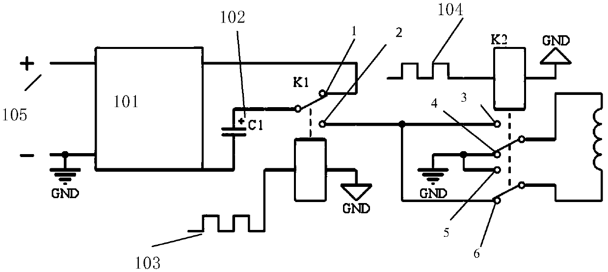
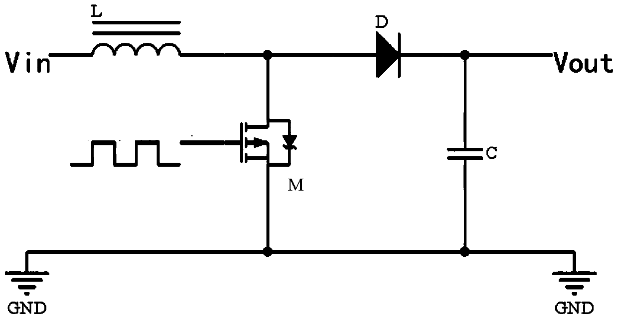
[0017] An embodiment of the present invention provides a voltage control circuit, which includes: a boost circuit module, a capacitor energy storage circuit module, a first relay module, and a second relay module, the boost circuit module is connected to a DC power supply, and the capacitor The energy storage circuit module is connected in series with the boost circuit module; the first relay module can be connected to the capacitor energy storage circuit module and the boost circuit module so that the capacitor energy storage circuit module is in a charging state, or connected to the capacitor energy storage circuit module The energy storage circuit module and the second relay mod...


PUM


Abstract

The invention discloses a voltage control circuit. The voltage control circuit comprises a boost circuit module, a capacitor energy storage circuit module, a first relay module and a second relay module; the boost circuit module is connected with a direct-current power supply; the capacitor energy storage circuit module is connected with the boost circuit module in series; the first relay module can be connected with the capacitor energy storage circuit module and the boost circuit module, so that the capacitor energy storage circuit module is enabled to be in a charging state, or, the first relay module can be connected with the capacitor energy storage circuit module and the second relay module, so that the capacitor energy storage circuit module is enabled to be in a discharge state; and the second relay module is connected with a load and at least can enable the capacitor energy storage circuit module to output forward or reverse current to the load. The invention further providesan electric control permanent magnet controller adopting the voltage control circuit. The electric control permanent magnet controller has the advantages of small size, accurate control and the like.

Description

technical field [0001] The invention particularly relates to a voltage control circuit and an electronically controlled permanent magnet controller, belonging to the technical field of electronically controlled magnetic force. Background technique [0002] The electronically controlled magnetic force product is an updated version of the traditional electromagnetic product. It has the advantages of large magnetic attraction and small size, and only needs to supply power at the moment of the charging / demagnetization function conversion, which not only saves a lot of power, but also reduces the loss caused by the coil being energized for a long time. The thermal deformation of the workpiece caused by the heating of the coil. The electronically controlled permanent magnet device controller is the core device of the electronically controlled magnetic force product, and its performance directly affects the overall performance and use safety of the electronically controlled magneti...

Claims


Application Information

Patent Timeline
Patent Type & Authority Applications(China)
IPC IPC(8): H02J7/00H02M3/07H02M3/156
CPCH02M3/073H02M3/156
Inventor 许珍林旻李金恩闫阿儒
Owner NINGBO INST OF MATERIALS TECH & ENG CHINESE ACADEMY OF SCI
Why Eureka
Try Eureka