Stator modular hybrid excitation consequent pole flux reverse motor

A technology of mixed excitation and magnetic flux reversal, applied in the direction of magnetic circuits, electric components, electrical components, etc., can solve the problems of high risk of permanent magnet demagnetization, high cost of permanent magnet use, difficulty in high-speed and weak magnetic operation, etc., to reduce demagnetization Risk, convenient modular processing, and the effect of improving mass production capacity

Inactive Publication Date: 2020-04-28
NANJING UNIV OF AERONAUTICS & ASTRONAUTICS
View PDF6 Cites 9 Cited by
  • Summary
  • Abstract
  • Description
  • Claims
  • Application Information

AI Technical Summary

Problems solved by technology

However, limited by the power level of the inverter, it is difficult to achieve high-speed field-weakening operation, which has become a factor limiting the application of this type of motor
In addition, existing flux reversal motors still have defects such as low torque density, high risk of permanent magnet demagnetization, low operational reliability, and high cost of permanent magnets.

Method used


Image

  • Stator modular hybrid excitation consequent pole flux reverse motor
  • Stator modular hybrid excitation consequent pole flux reverse motor
  • Stator modular hybrid excitation consequent pole flux reverse motor

Examples


Embodiment 1

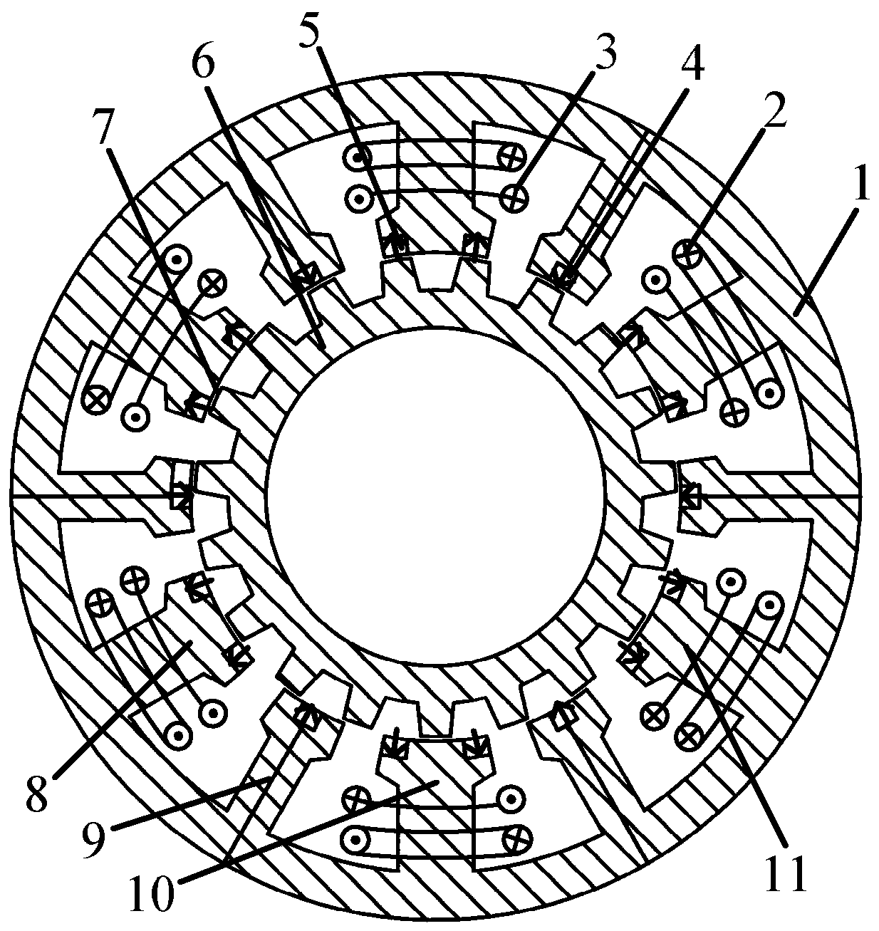
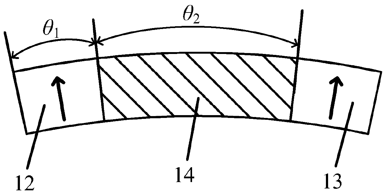
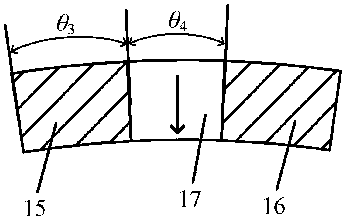
[0028] Such as figure 1 As shown, two permanent magnets with the same polarity are pasted on the two side edges of the surface of the large stator teeth, and a salient pole stator core is formed between the two permanent magnets. The cores form an alternating pole stator structure. A permanent magnet is pasted in the middle of the surface of the small stator teeth. Two salient pole stator cores are formed on both sides of the permanent magnet. The two salient pole stator cores and the permanent magnets between them form an alternating pole stator structure. . Such as figure 2 As shown, the pole arcs (θ 1 )same. Such as image 3 As shown, the pole arcs (θ 3 )same. By adjusting the pole arc θ of the permanent magnet 12 1 , pole arc θ of salient pole core 14 2 , Pole arc θ of permanent magnet 17 4 and the pole arc θ of the salient pole core 15 3 , can adjust the output electromagnetic performance and magnetic modulation performance of the permanent magnet of the motor...

Embodiment 2

[0031] Such as Figure 4 As shown, a permanent magnet is pasted in the middle of the surface of the large stator teeth. Two salient pole stator cores are formed on both sides of the permanent magnet. The two salient pole stator cores and the permanent magnets in between form an alternating Pole stator structure; two permanent magnets with the same polarity are pasted on the two side edges of the surface of the small stator teeth, and a salient pole stator core is formed between the two permanent magnets, and the salient pole stator core between the two permanent magnets and the The iron core forms an alternating pole stator structure. Similarly, the pole arcs of the two salient pole stator cores on the large stator teeth are the same, and the pole arcs of the two permanent magnets on the small stator teeth are the same.

[0032] combine figure 1 Describe how the windings of this motor are connected. Taking the three-phase armature winding as an example, in order to eliminat...


PUM


Abstract

The invention discloses a stator modular hybrid excitation consequent pole flux reverse motor. The motor comprises a plurality of modular stators and an inner rotor, the plurality of modular stators are tightly attached in sequence to form a complete outer stator; an independent air gap is formed between the outer stator and the inner rotor; a plurality of stator grooves are formed in the outer stator; and stator teeth are formed between adjacent stator grooves. The stator teeth are divided into large stator teeth and small stator teeth according to the size; the large stator teeth and the small stator teeth are arranged adjacently; permanent magnets are attached to the surface of each large stator tooth and the surface of each small stator tooth, the width of each permanent magnet is smaller than that of the surface of the corresponding stator tooth, the polarity of the permanent magnet on each large stator tooth is opposite to that of the permanent magnet on the adjacent small statortooth, and an armature winding and a direct-current excitation winding are wound on each large stator tooth. According to the invention, the problems of low torque density and permanent magnet demagnetization of the flux reversal motor are solved, the electromagnetic performance and the operation reliability of the motor are improved, and the processing cost of the motor is reduced.

Description

technical field [0001] The invention belongs to the field of motors, and in particular relates to a mixed excitation magnetic flux reversal motor. Background technique [0002] Due to the use of high magnetic energy permanent magnets, the permanent magnet motor has the advantages of high torque density, high power density, good weak magnetic performance and high efficiency, and is suitable for operation in the full speed range. The flux reversal motor with permanent magnets attached to the surface of the stator teeth has been widely studied due to the advantages of high mechanical strength of the rotor and easy heat dissipation when the permanent magnets are attached to the stator teeth. It has broad application prospects in electric vehicles and other application fields. However, limited by the power level of the inverter, it is difficult to achieve high-speed field-weakening operation, which has become a factor limiting the application of this type of motor. In addition, ...

Claims


Application Information

Patent Timeline
Patent Type & Authority Applications(China)
IPC IPC(8): H02K1/14H02K1/16H02K1/17H02K1/24
CPCH02K1/148H02K1/16H02K1/17H02K1/24H02K2201/03H02K2213/12
Inventor 王凯孙海阳李烽孔金旺张建亚张琳
Owner NANJING UNIV OF AERONAUTICS & ASTRONAUTICS
Why Eureka
Try Eureka