
A wireless automatic calibration device and calibration method for CT loop

An automatic calibration and primary circuit technology, applied in the power industry, can solve problems such as unclear CT polarity errors, potential safety hazards, and increased on-site accident hazards, so as to reduce technical capability requirements, reduce weight and volume, and facilitate on-site carrying effect

Active Publication Date: 2020-07-31
BEIJING RUICHUANG XINZHI TECH CO LTD
View PDF5 Cites 0 Cited by
  • Summary
  • Abstract
  • Description
  • Claims
  • Application Information

AI Technical Summary

Problems solved by technology

[0008] 1. Although it is known that one of the two CTs must have the wrong polarity, it is not clear which CT has the wrong polarity, and other methods need to be further verified;
[0009] 2. Even if the differential current is 0, it cannot be judged that the polarity of the CT must be correct, because it is possible that the polarity of both CTs is wrong;
And when the primary loop impedance is large, it is very difficult to increase the primary current output by the large current generator;
[0011] 4. This method cannot determine the polarity of the CT circuit without differential current calculation, such as circuit breaker protection CT
[0015] First, the voltage in the test circuit is about 60V, which is higher than the human body safety voltage of 36V, and there are potential safety hazards; Recover the accident of changing the circuit; third, the distance from the calibration device of the primary equipment site to the protection and automatic device of the secondary equipment chamber is relatively long, and there are various primary high-voltage equipment, and there is a great safety risk in connecting them through wires
Therefore, many application units are more taboo about this method, and have not been widely used in the field.

Method used


Image

  • A wireless automatic calibration device and calibration method for CT loop
  • A wireless automatic calibration device and calibration method for CT loop
  • A wireless automatic calibration device and calibration method for CT loop

Examples


Embodiment Construction

[0058] In order to make the purpose, technical solutions and advantages of the embodiments of the present invention clearer, the technical solutions in the embodiments of the present invention will be clearly and completely described below in conjunction with the drawings in the embodiments of the present invention. Obviously, the described embodiments It is a part of embodiments of the present invention, but not all embodiments. Based on the embodiments of the present invention, all other embodiments obtained by persons of ordinary skill in the art without creative efforts fall within the protection scope of the present invention.

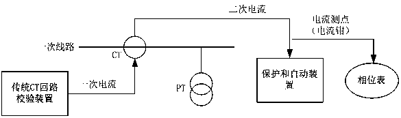
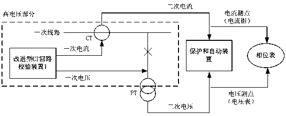
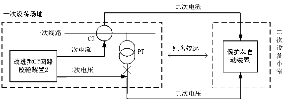
[0059] In order to solve the problem that the current CT loop calibration device cannot completely complete the current vector test, the embodiment of the present invention provides a CT loop wireless automatic calibration device, and proposes a corresponding testing method.

[0060] An embodiment of the present invention provides a schematic stru...


PUM


Abstract

The invention provides a CT loop wireless automatic verification device and method. The CT loop wireless automatic verification device is divided into two parts which are a signal generating device and a signal measuring device. The signal generating device can automatically generate the amplitude and phase of a primary current and a reference voltage according to electrical parameters of the primary circuit under test and judges whether the current CT loop is correct or not according to CT vector measurement results returned by the signal measuring device. The signal measuring device can receive a virtual voltage sent by the signal generating device through a wireless mode, accurately measure the CT vector, and wirelessly feed back the CT vector measurement results to the signal generating device. The CT loop wireless automatic verification device can easily, safely and automatically judge the transformation ratio error and the polarity error appearing in the CT loop, and the technical defects that an excessive voltage in a test loop in the prior art, needing of modifying a primary circuit or a secondary circuit during the test process, and the safety risks caused by the use of long cables are overcome.

Description

technical field [0001] The invention relates to the technical field of electric power industry, in particular to the technical field of secondary system testing in substations, in particular to a CT loop calibration device and calibration method. Background technique [0002] The secondary system in the substation is large in scale, and the protection configuration and CT circuit are relatively complicated. In the test, problems such as CT polarity reverse connection and transformation ratio connection error often occur, which have a negative impact on the commissioning progress and quality. [0003] In the on-site commissioning of the secondary system of the substation, the correctness of the circuit is usually guaranteed by means of checking the wiring, testing the circuit resistance and the polarity of the point CT, but the above methods are all indirect testing methods, and multiple test results are required to confirm each other. Final test conclusion. Moreover, it is ...

Claims


Application Information

Patent Timeline
Patent Type & Authority Patents(China)
IPC IPC(8): G01R35/02G01R19/04G01R31/72H02H7/045H02H7/26
CPCG01R19/04G01R35/02H02H7/045H02H7/263
Inventor 邹学灿
Owner BEIJING RUICHUANG XINZHI TECH CO LTD
Learn More