
Lifting and transferring machinery for construction of construction site

A construction site and machinery technology, applied in the field of lifting and transferring machinery for construction site construction, can solve the problems of too simple structure, prone to failure, threatening the personal safety of staff, etc. Effect

Inactive Publication Date: 2020-05-05
枣庄职业学院
View PDF6 Cites 3 Cited by
  • Summary
  • Abstract
  • Description
  • Claims
  • Application Information

AI Technical Summary

Problems solved by technology

[0004] The purpose of the present invention is to solve the problem that the existing design structure is too simple, easy to break down, and there is no safety self-locking device, and it is easy to cause damage to items or even threaten the personal safety of workers when mechanical failure occurs. Lifting and transferring machinery for construction, the structure of the present invention is safer and more practical, and can better protect property and personal safety in the event of mechanical failure

Method used


Image

  • Lifting and transferring machinery for construction of construction site
  • Lifting and transferring machinery for construction of construction site
  • Lifting and transferring machinery for construction of construction site

Examples


Embodiment 1

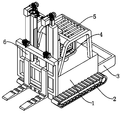
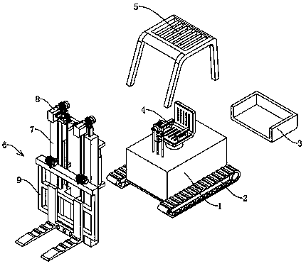
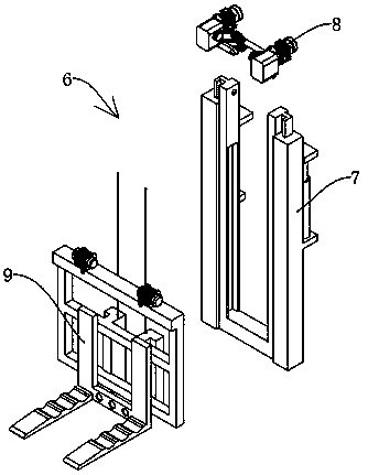
[0027] see Figure 1-4, a lifting transfer machine for construction site construction, comprising a machine main body 1 and a traveling crawler belt 2, the traveling crawler belt 2 is fixedly installed on both sides of the lower end of the machine main body 1, a carrying box 3 is fixedly connected to the tail of the machine main body 1, and the machine main body 1 A driver's cab 4 is arranged above, and a driver's seat and a control device are fixedly installed inside the driver's cab 4, and a protective frame 5 is fixedly connected around the driver's cab 4; a lifting transfer device 6 is connected to the front end of the machine body 1, and the lifting transfer device 6 includes Hydraulic lifting mechanism 7, cable driving mechanism 8 and cable lifting mechanism 9, hydraulic lifting mechanism 7 is connected on the mechanical main body 1, and cable driving mechanism 8 and cable lifting mechanism 9 are connected on the hydraulic lifting mechanism 7.

[0028] The hydraulic lift...

Embodiment 2

[0031] see Figure 5 , based on Embodiment 1, the difference is that;

[0032] The cable driving mechanism 8 includes a servo lifting motor 801, the servo lifting motor 801 is fixedly connected to the top of the connecting rod 703, the tail of the servo lifting motor 801 is fixedly connected with an electromagnetic brake 817, and the end of the servo lifting motor 801 away from the electromagnetic brake 817 is provided with a Mounting case 802, mounting case 802 is also fixedly connected with connecting rod 703, the inside of mounting case 802 is provided with pinion 803, pinion 803 is fixedly connected on the output shaft of servo lifting motor 801, and pinion 803 is meshed with big gear 804 .

[0033] The large gear 804 is fixedly connected to the first worm 805, and the first worm 805 rotates inside the installation shell 802. The first worm 805 is meshed with the first worm wheel 806, and the first worm wheel 806 is fixedly connected to the first connecting shaft 807. A ...

Embodiment 3

[0037] refer to Figure 6 ; Based on Embodiment 1 or 2, the difference is that;

[0038] The cable lifting mechanism 9 includes a fixed rod 901 and a lifting cable 902. The fixed rod 901 is slidably connected to the mounting groove 707. The bottom end of the lifting cable 902 is fixedly connected to the top of the fixing rod 901. The upper end of the lifting cable 902 is wound and connected to On the winding roller 816, the fixed rod 901 is also fixedly connected with a connecting frame 903, the connecting frame 903 is fixedly connected with a lifting transfer frame 904, and the bottom of the lifting transfer frame 904 is fixedly connected with an auxiliary fixing frame 905, and the auxiliary fixing frame 905 is set There are fixing holes, and an electric winch 906 is fixedly installed on the top of the connecting frame 903 , and the electric winch 906 is matched with the auxiliary fixing frame 905 .

[0039] The cable lifting mechanism 9 of the present invention is matched w...


PUM


Abstract

The invention discloses a lifting and transferring machinery for construction of a construction site and belongs to the technical field of building machinery. The lifting and transferring machinery comprises a machinery main body and marching tracks, wherein the marching tracks are fixedly mounted on the two sides of the lower end of the machinery main body; a carrying box is fixedly connected with the tail part of the machinery main body; a cab is arranged above the machinery main body; a driving seat and a control device are fixedly mounted in the cab; a protective rest is fixedly connectedwith the periphery of the cab; a lifting and transferring device is connected with the front end of the machinery main body and comprises a hydraulic lifting mechanism, a wire rope driving mechanism and a wire rope lifting mechanism; the hydraulic lifting mechanism is connected onto the machinery main body; and the wire rope driving mechanism and the wire rope lifting mechanism are connected ontothe hydraulic lifting mechanism. The lifting and transferring machinery effectively solves the problems that the existing design structure is excessively simple, likely to break down and is not provided with an insurance self-locking device, as a result, the article is likely to be damaged and even the personal safety of a worker is threatened if a mechanical failure takes place.

Description

technical field [0001] The invention relates to the technical field of construction machinery, in particular to a lifting and transferring machine for construction on a construction site. Background technique [0002] Explanation of construction machinery terms: Construction machinery is the general term for mechanical equipment used in engineering construction and urban and rural construction. It is also called "construction machinery" and "construction machinery" in China. It is time-consuming and labor-intensive to rely on manual handling for lifting or transferring, the efficiency is very low, and it is prone to danger. In order to solve these problems, it is very necessary to design a lifting and transferring machine for construction site construction. [0003] At present, the lifting and transferring machines for construction site construction that already exist on the market often use hydraulic systems or chain drives to realize the lifting and transferring of mechani...

Claims


Application Information

Patent Timeline
Patent Type & Authority Applications(China)
IPC IPC(8): B66F9/06B66F9/075B66F9/12B66F9/18B66F9/20B66F9/22B66F9/24B62D55/065
CPCB62D55/065B66F9/06B66F9/075B66F9/07513B66F9/07554B66F9/12B66F9/122B66F9/18B66F9/20B66F9/22B66F9/24
Inventor 丁晓东万军贾百川杨南付志刚
Owner 枣庄职业学院
Learn More