High-strength bolt connection arc end plate slippage friction energy consumption column base joint

A high-strength bolt and friction energy-dissipating technology, applied in the direction of columns, pier columns, pillars, etc., can solve the problems of plastic damage of column foot joints, loss of building function, and repair of permanent structural deformation, so as to avoid welding operations and engineering Efficient construction, avoiding plastic deformation and damage

Inactive Publication Date: 2020-05-05
WUHAN UNIV OF SCI & TECH
View PDF5 Cites 1 Cited by
  • Summary
  • Abstract
  • Description
  • Claims
  • Application Information

AI Technical Summary

Problems solved by technology

The plastic damage of the column base joints will cause severe permanent deformation of the structure, making it difficult or difficult to repair. The cost of repair or demolition itself is very huge, and the loss or suspension of the building's use function due to column base damage will cause social and economic life. It cannot be carried out normally, and the indirect economic loss caused by it cannot be estimated

Method used


Image

  • High-strength bolt connection arc end plate slippage friction energy consumption column base joint
  • High-strength bolt connection arc end plate slippage friction energy consumption column base joint
  • High-strength bolt connection arc end plate slippage friction energy consumption column base joint

Examples


Embodiment approach

[0028] As one of the implementation methods, the upper and lower arc end plates are convex arc plates, the bolt holes of the upper arc end plate are oblong bolt holes, the bolt holes of the lower arc end plate are standard round holes, the lower steel columns are of equal cross-section, and the thickness of the upper and lower steel columns is same.

[0029] As one of the implementation methods, the upper and lower arc end plates are concave arc plates, the bolt holes of the upper arc end plate are oblong bolt holes, the bolt holes of the lower arc end plate are standard round holes, the lower steel columns are of equal cross-section, and the thickness of the upper and lower steel columns is same.

[0030] As one of the implementation methods, the upper and lower arc end plates are convex arc plates, the bolt holes of the upper arc end plate are oblong bolt holes, the bolt holes of the lower arc end plate are standard round holes, the lower steel columns are of variable cross-...

Embodiment 1

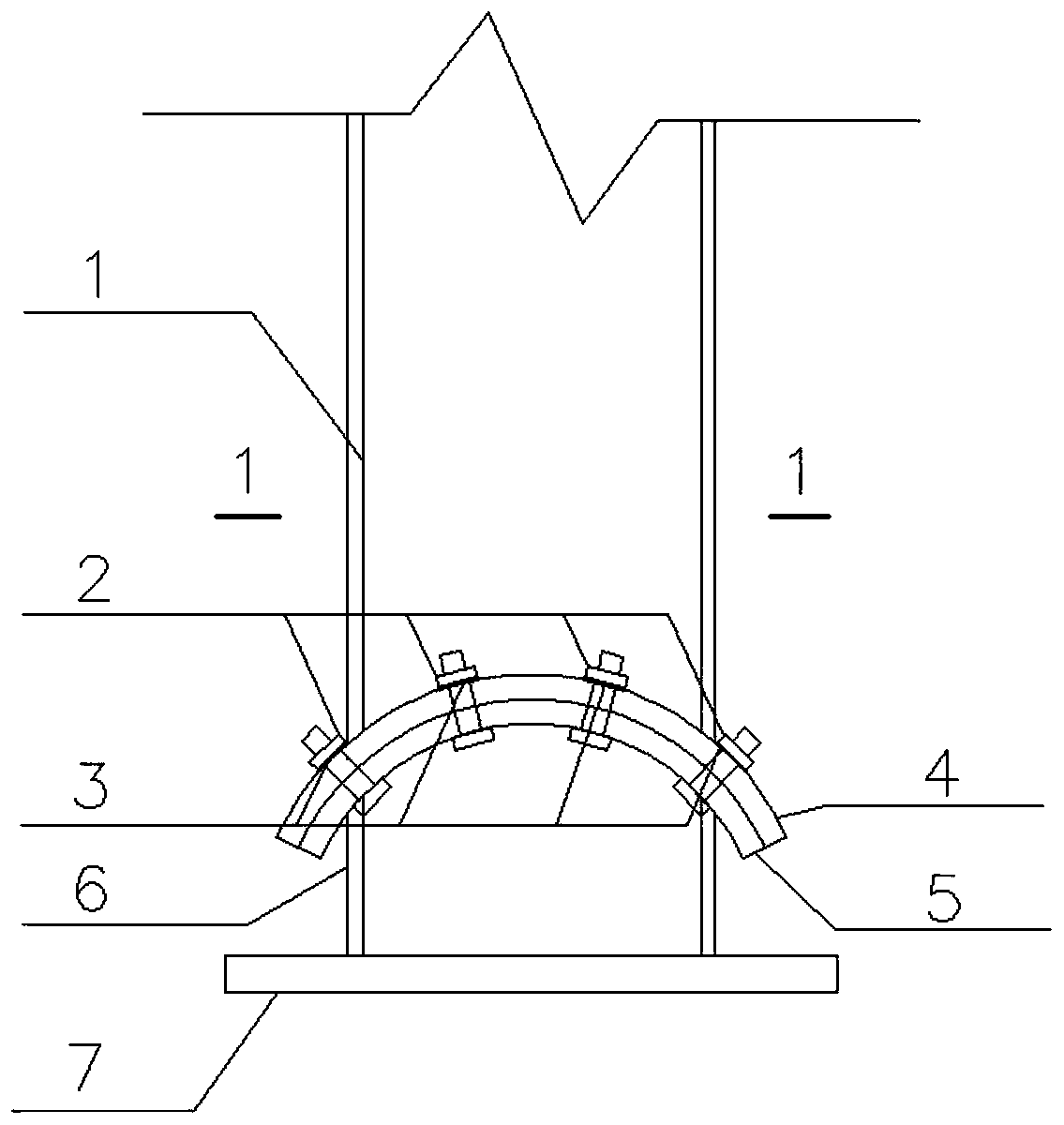
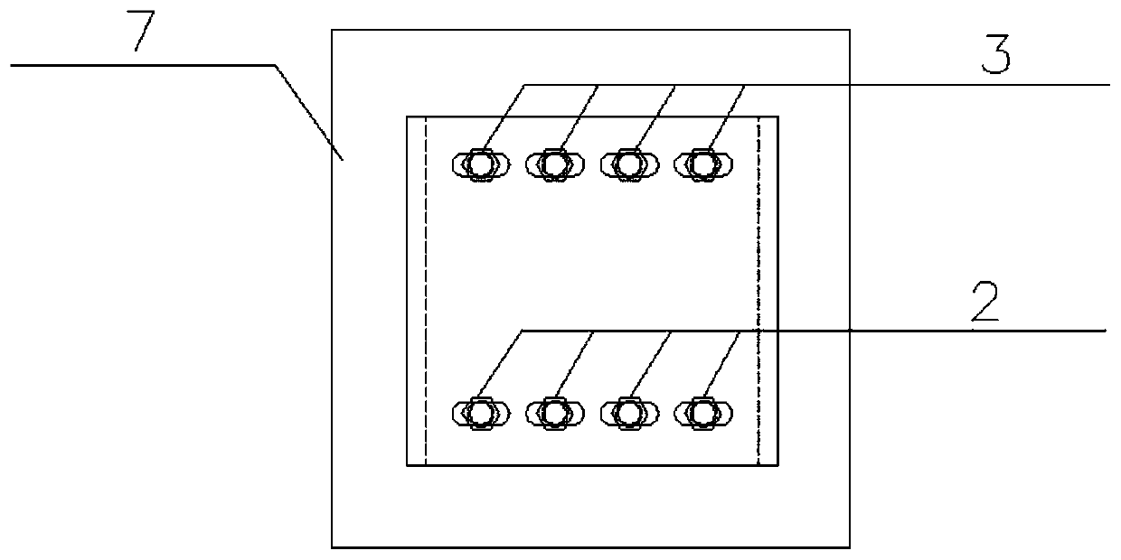
[0035] see figure 1 , image 3 , The arc-shaped end plate connection node is composed of an upper steel column 1, a high-strength bolt 2, a disc spring 3, an upper arc end plate 4, a lower arc end plate 5, a lower steel column 6, and a bottom plate 7. Wherein, the upper arc end plate 4 adopts oblong bolt holes, and the lower arc end plate 5 adopts standard round holes. The upper steel column 1 and the upper arc end plate 3, the lower steel column 5 and the lower arc end plate 4 are all welded by weld seams, and the disc spring 3 is set on the screw rod of the high-strength bolt 2 and placed under the nut. Disc spring 3 , upper arc end plate 4 and lower arc end plate 5 are connected by high-strength bolts 2 . The bolt hole diameters and the bolt hole spacing between the disc spring 3 , the upper arc end plate 4 and the lower arc end plate 5 correspond one-to-one.

[0036] In the connection nodes mentioned above, the steel of the upper steel column 1 and the lower steel colum...

Embodiment 2

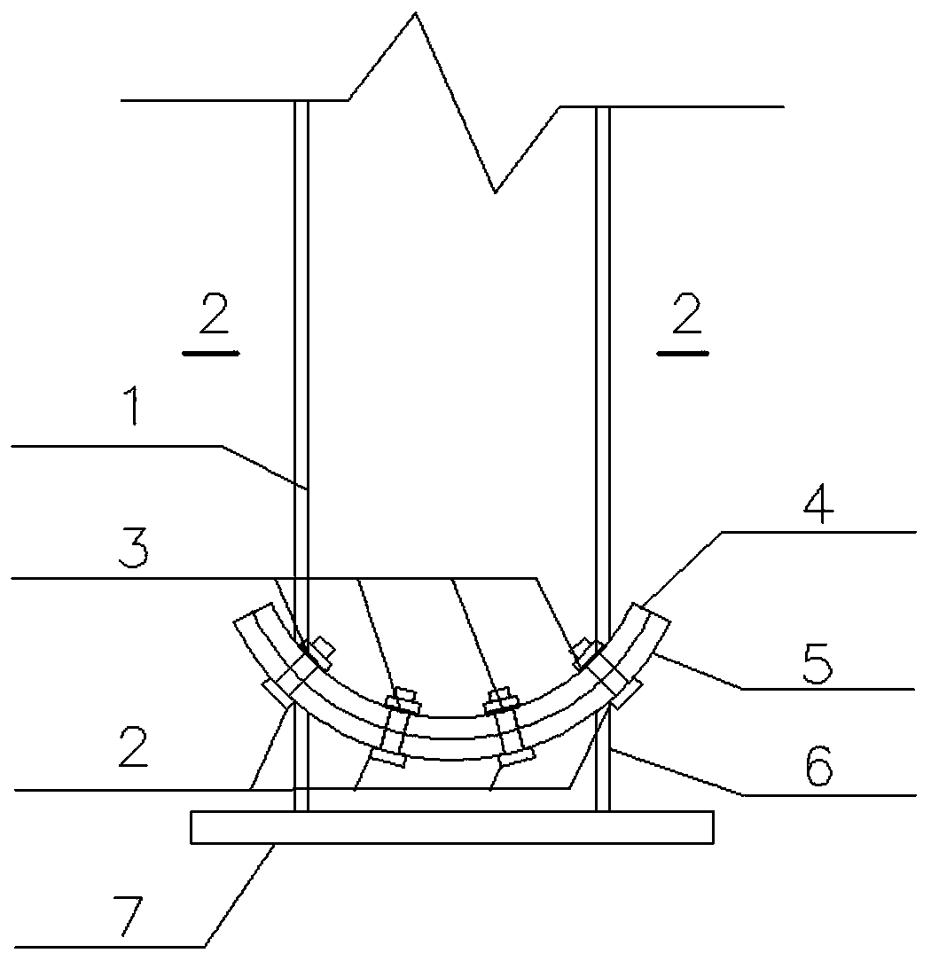
[0063] see figure 2 , Figure 4 , the design method and theoretical calculation method of this embodiment are the same as those of Example 1, and will not be repeated here. Different from Embodiment 1, the upper arc end plate 4 and the lower arc end plate 5 both adopt concave end plates.

[0064] Through the finite element simulation of ANSYS, it can be seen that Figure 9 The hysteresis curve shown is close to a parallelogram, which reflects the large slip deformation characteristics of the nodes. When the load is reversed after unloading, the stiffness of the joints still does not decrease, indicating that the overall stiffness degrades little. The shape of the hysteretic curve is full without pinching, indicating that the joint form has good deformation capacity and energy dissipation capacity, and the bearing capacity of the concave joint is slightly lower than that of the convex joint.


PUM


Abstract

The invention discloses a high-strength bolt connection arc end plate slippage friction energy consumption column base joint, and belongs to the technical field of building engineering and steel structures. The joint is composed of a steel column, two arc end plates and a high-strength bolt. The steel column and the arc plates are in welded line connection. The invention provides a manufacturing method of the high-strength bolt connection arc end plate slippage friction energy consumption column base joint. The joint is the assembled joint, the manner is simple, site construction is convenient, the joint can rotate, an interface generates slippage friction, earthquake energy is dissipated, in the rotating process, the joint is in the elastic state, and the plastic deforming and damage appearing in an after-earthquake structure can be avoided to the maximum degree.

Description

technical field [0001] The invention belongs to the technical field of building structure engineering, and specifically refers to a high-strength bolt-connected arc-shaped end plate sliding friction energy-dissipating column base node. Background technique [0002] When an earthquake occurs, the traditional high-strength bolted column base joints dissipate the seismic energy through the destruction of the bolts and the yielding or even fracture and destruction of the rods. The plastic damage of the column base joints will cause severe permanent deformation of the structure, making it difficult or difficult to repair. The cost of repair or demolition itself is very huge, and the loss or suspension of the building's use function due to column base damage will cause social and economic life. It cannot be carried out normally, and the indirect economic losses caused are even more unpredictable. In this context, the seismic design of "damage control based on minimum loss" is of ...

Claims


Application Information

Patent Timeline
Patent Type & Authority Applications(China)
IPC IPC(8): E04C3/32E04B1/98E04H9/02
CPCE04B1/98E04C3/32E04H9/021E04H9/024
Inventor 刘琪李成玉向傲磊袁双双胡天炜陈修远
Owner WUHAN UNIV OF SCI & TECH
Why Eureka
Try Eureka