Inserting plate rotor engine

A technology of rotor engine and plug-in plate, which is applied in the direction of combustion engine, machine/engine, internal combustion piston engine, etc. It can solve the problems of heavy pollution, heavy weight, and poor sealing, and achieve low wear and power consumption, simple structure, and tightness. Good results

Inactive Publication Date: 2020-05-05
苗靖文
View PDF0 Cites 1 Cited by
  • Summary
  • Abstract
  • Description
  • Claims
  • Application Information

AI Technical Summary

Problems solved by technology

[0003] The purpose of the present invention is to provide a reciprocating piston engine to overcome defects such as large volume, heavy weight, and low efficiency caused by unreasonable structure, as well as defects such as poor sealing, high fuel consumption, and large pollution of the existing rotary engine scheme, and provide a plug-in engine. plate rotor engine

Method used


Image

  • Inserting plate rotor engine
  • Inserting plate rotor engine
  • Inserting plate rotor engine

Examples


Embodiment 1

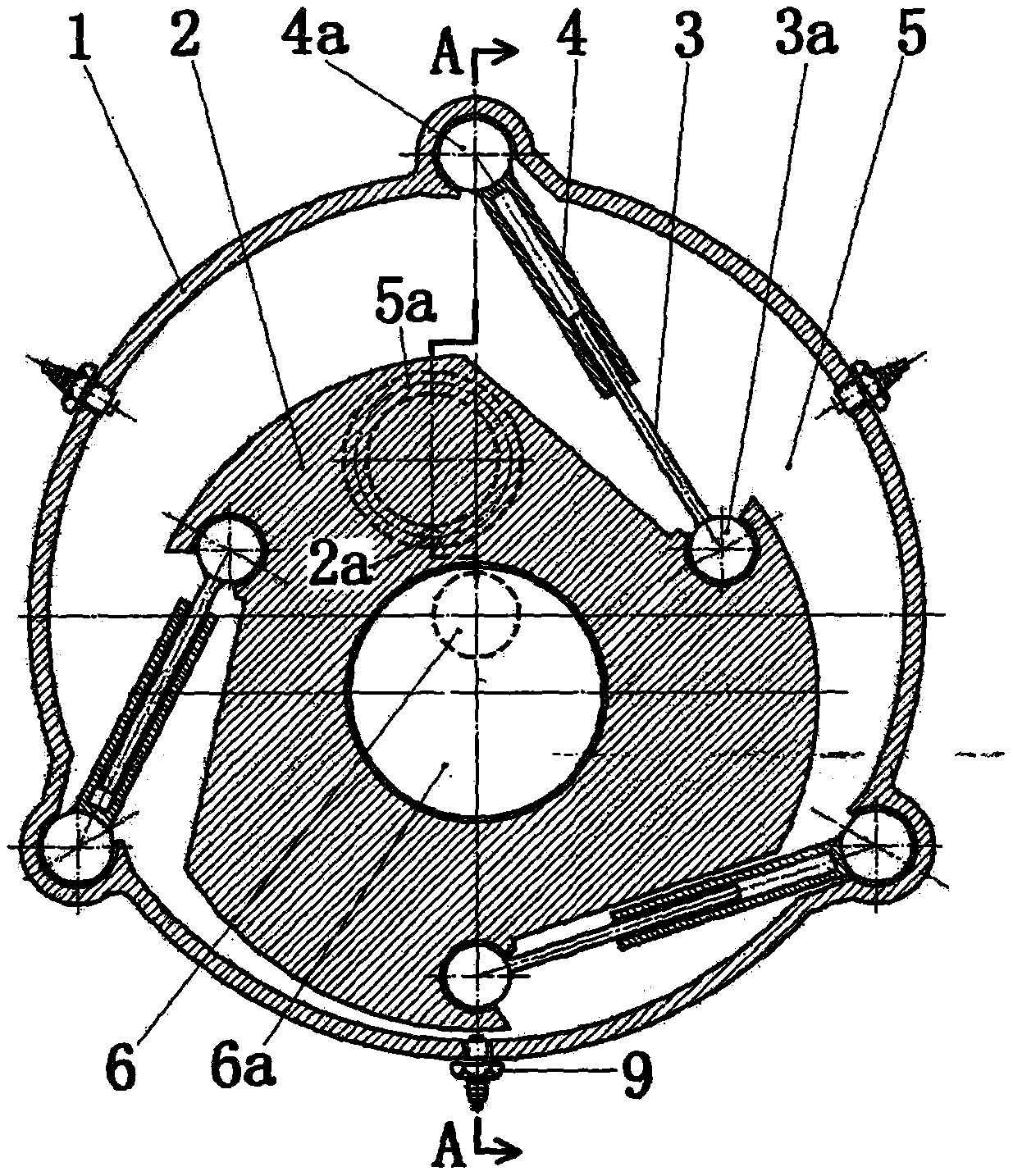
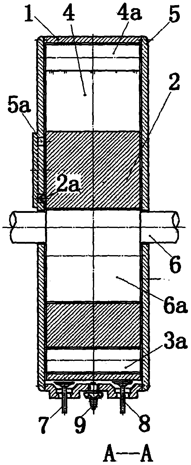
[0015] Such as figure 1 , 2 As shown, a plug-in rotor engine mainly includes a casing 1 , a rotor 2 , a plug-in plate 3 and a slot 4 . The two ends of the fixed cylindrical casing are closed by end covers 5, and a main shaft 6 is located at the axis of the casing, and the main journals at both ends are respectively supported on the end covers on both sides, and are located between the inner walls of the two end covers. The first section of the main shaft is the eccentric shaft 6a, on which the rotor with a cylindrical appearance is set. Both ends of the eccentric shaft and the rotor are close to the inner wall of the end cover for sliding and sealing fit. On the inner wall of the casing, use the slotted shaft 4a Evenly distributed hinged There are three axially long slots for swinging, the slots are inwards, and both ends of the slots are open, and on the outer wall of the rotor, they are hinged outwards evenly by the inserting plate shaft 3a There are three axially long ins...

Embodiment 2

[0028] Such as image 3 As shown, four pairs of plugboards 3 and slots 4 are provided in the plugboard rotor engine, and four sets of intake valves 7, exhaust valves 8 and spark plugs 9 are correspondingly provided. Part and its working principle are all the same as in Embodiment 1.

Embodiment 3

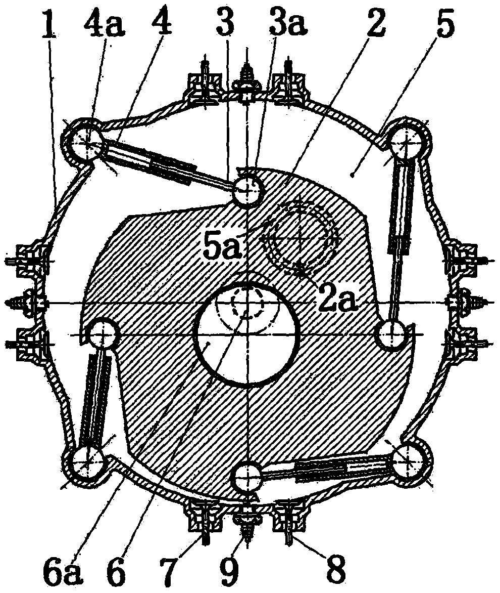
[0030] Such as Figure 4 As shown, there are six pairs of plug-in plates 3 and slots 4 in the plug-in rotor engine, and correspondingly there are six sets of intake valves 7, exhaust valves 8 and spark plugs 9. Part and its working principle are all the same as in Embodiment 1.


PUM


Abstract

The invention discloses an inserting plate rotor engine. A spindle (6) is arranged on the axis of a cylindrical case (1) with the two ends closed by end covers (5), a cylindrical rotor (2) is mountedon an eccentric shaft (6a) on the spindle in a sleeving mode, no less than three inserting grooves (4) with inward groove openings are hinged to the inner wall of the case in an even distribution mode, inserting plates (3) matched with the inserting grooves are outwards hinged to the outer wall of the rotor in an even distribution mode, the two ends of the eccentric shaft, the two ends of the rotor, the two ends of the inserting grooves and the two ends of the inserting plates are closely attached to the inner walls of the end covers correspondingly for sliding fit, all the inserting plates are inserted into the corresponding inserting grooves, an interlayer between the rotor and the case is divided into a plurality of closed cavities which are each provided with an intake valve (7), an exhaust valve (8) and a spark plug (9) to serve as engine air cylinders, and the volume of each air cylinder is periodically increased and decreased along with rotation of the spindle to complete the air suction, compression, work and exhaust stroke to drive the spindle to do work. The inserting plate rotor engine is large in power, small in size and simple in structure.

Description

[0001] Technical Field: The present invention relates to an engine, in particular to a plug-in rotor engine. Background technique [0002] The reciprocating piston engine has many reciprocating parts, and the crank and connecting rod mechanism is heavy, resulting in its harmful inertia, large volume and weight, resulting in large internal resistance, high power consumption, large vibration, and fast wear, while the rotary engine can directly output rotation Power, no reciprocating parts and crank connecting rod, simple structure, few parts, small size, light weight, high power density, stable output, low vibration and noise, can effectively overcome the above-mentioned defects of reciprocating engines, people have been committed to research All kinds of rotary engines have been stranded due to various problems such as sealing. Only one kind of Wankel triangular rotary engine has been used in a small amount, but this engine also has its structural fatal flaws: 1. Because the pro...

Claims


Application Information

Patent Timeline
Patent Type & Authority Applications(China)
IPC IPC(8): F02B53/02F02B55/02F02B53/06F02B55/08F02B55/14
CPCF02B53/02F02B53/06F02B55/02F02B55/08F02B55/14Y02T10/12
Inventor 苗靖文
Owner 苗靖文
Why Eureka
Try Eureka