
Oil circuit structure of sliding bearing

A sliding bearing and oil circuit technology, which is applied in the field of the oil circuit structure of the sliding bearing, can solve the problems of large oil pool volume and low heat exchange efficiency, etc.

Active Publication Date: 2021-09-14
HUNAN CHONGDE IND TECH
View PDF6 Cites 0 Cited by
  • Summary
  • Abstract
  • Description
  • Claims
  • Application Information

AI Technical Summary

Problems solved by technology

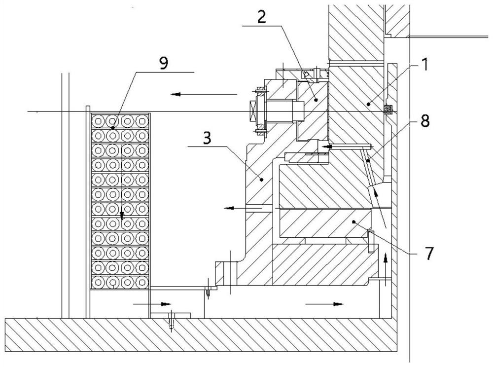
The heat transfer efficiency of the heat conduction heat transfer method is low, resulting in a large volume of the oil pool 1 and the oil-water cooler 9 required

Method used


Image

  • Oil circuit structure of sliding bearing
  • Oil circuit structure of sliding bearing
  • Oil circuit structure of sliding bearing

Examples


Embodiment Construction

[0023] Specific embodiments of the present invention will be described in detail below in conjunction with the accompanying drawings. It should be understood that the specific embodiments described here are only used to illustrate and explain the present invention, and are not intended to limit the present invention.

[0024] For the convenience of description, spatially relative terms may be used here, such as "on ...", "over ...", "on the surface of ...", "above", etc., to describe the The spatial positional relationship between one device or feature shown and other devices or features. It will be understood that the spatially relative terms are intended to encompass different orientations of the device in use or operation in addition to the orientation depicted in the figures. For example, if the device in the figures is turned over, devices described as "above" or "above" other devices or configurations would then be oriented "beneath" or "above" the other devices or conf...


PUM


Abstract

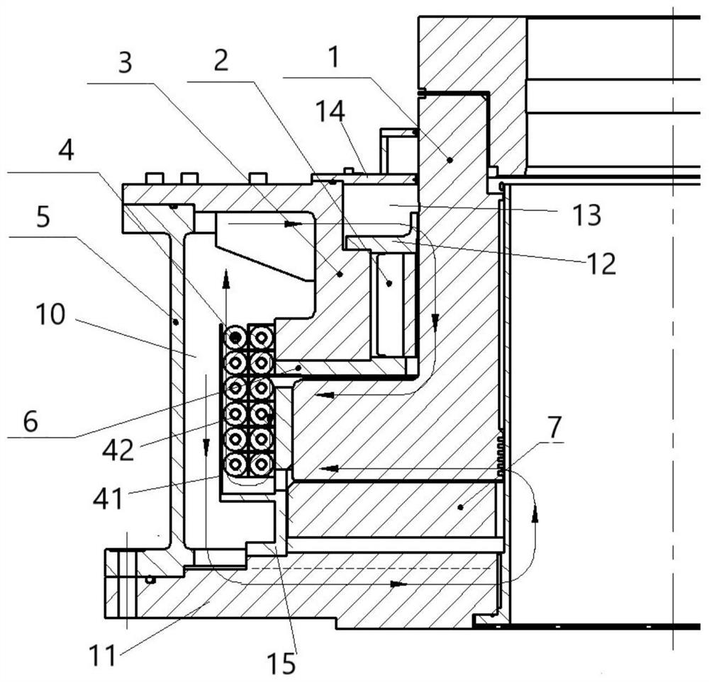
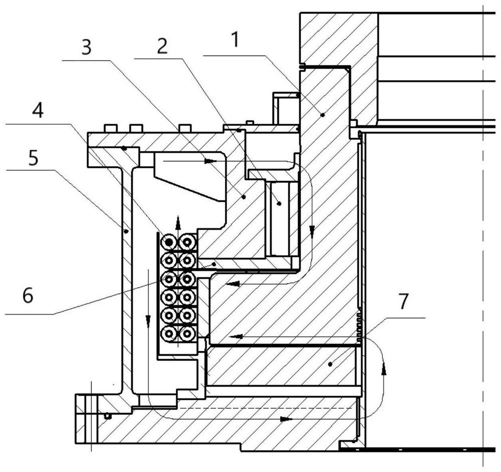
The invention provides an oil circuit structure of a sliding bearing, including a cooling device, a thrust head, a thrust shoe and a pressure plate sleeved outside the rotating shaft. There is a first gap between the big end and the thrust pad, and there is a second gap between the big end and the pressure plate. The cooling device is located in the oil tank filled with lubricating oil. The cooling device includes an outer partition and multiple A cooling pipe, the outer partition is surrounded by a space with an inlet and outlet, the inlet and outlet are connected to the oil tank, a plurality of cooling pipes are located in the space surrounded by the outer partition, one end of the first gap and one end of the second gap are connected In the space enclosed by the outer partition, the other end of the first gap and the other end of the second gap communicate with the oil tank through the passage opened on the bearing. The invention forms two planar viscous pumps to provide driving force; the heat transfer efficiency of the cooler is improved, and the cooling effect of the bearing is improved.

Description

technical field [0001] The invention relates to the technical field of lubrication and cooling of sliding bearings, in particular to the oil passage structure of sliding bearings. Background technique [0002] When the existing sliding bearing self-lubricating oil supply, many use the centrifugal force of the through hole on the rotary thrust head immersed in the oil pool to supply oil, or the rotating shaft is driven by an impeller pump or a gear pump to provide power. The cooling efficiency of the lubricating oil in the above manner is low and the structure is not compact. Such as figure 1 As shown, the sliding bearing includes a guide seat 3, a thrust head 1, a thrust shoe 7 and a guide shoe 2, the thrust shoe 7 and the guide shoe 2 are located in the guide seat 3, one end of the thrust head 1 is located in the guide seat 3, and the other end Located outside the guide seat 3 , the end face of the thrust head 1 is in contact with the thrust shoe 2 , and the guide shoe 2 ...

Claims


Application Information

Patent Timeline
Patent Type & Authority Patents(China)
IPC IPC(8): F16C17/08F16C33/04F16C37/00
CPCF16C17/08F16C33/04F16C37/00
Inventor 刘小军宋清平冯毅周忺骄朱杰张亚宾张起楼卓乐罗薇凌黎周少华
Owner HUNAN CHONGDE IND TECH
Learn More