Three-dimensional radio frequency imaging system and method with real-time calibration

An imaging system and radio frequency technology, applied in radio wave measurement system, radio wave reflection/reradiation, utilization of reradiation, etc., can solve problems such as manual monitoring visual fatigue, privacy violation, large radio frequency bandwidth, etc.

Active Publication Date: 2020-05-05
徐立
View PDF8 Cites 5 Cited by
  • Summary
  • Abstract
  • Description
  • Claims
  • Application Information

AI Technical Summary

Problems solved by technology

This is because in the phased array implementation method, the distance between the antennas is half a wavelength, and it is a great challenge to place all the components and high-speed digital connections in this small area.
The resulting electromagnetic interference noise is coupled to the antenna of the array, which will directly reduce the sensitivity of the array
[0007] In addition to this, another problem is the identification and processing of a large number of image information
For example, in the anti-terrorist human body security radio frequency imaging system, the clothes of people are transparent and cannot cover the body, which violates people's privacy. In addition, a large amount of image information causes manual monitoring visual fatigue
[0008]The existing radio frequency imaging system for human security inspection generally uses linear frequency modulation to realize imaging, which needs to occupy a large radio frequency bandwidth to detect the distance from the target to the imaging system. The detection accuracy of the distance is directly related to the RF bandwidth, which is very unrealistic in practical applications

Method used


Image

  • Three-dimensional radio frequency imaging system and method with real-time calibration
  • Three-dimensional radio frequency imaging system and method with real-time calibration
  • Three-dimensional radio frequency imaging system and method with real-time calibration

Examples


Embodiment Construction

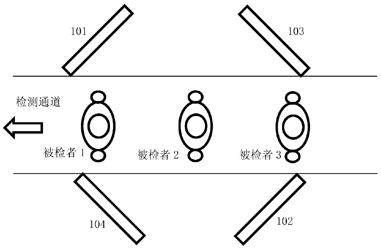
[0031] The schematic diagram of the human body security detector, one of the application examples of the real-time calibrated radio frequency imaging system, is shown in figure 1 . The four transceiver arrays 101 , 102 , 103 , 104 are arranged oppositely in pairs as shown in the figure, and the subjects to be tested pass through the detection channel in turn. Each transceiver array 101, 102, 103, 104 has its own transmission frequency set, such as F1, F2, F3, F4, each frequency set contains multiple frequencies, or frequency points, and these frequencies are not repeated , in order to achieve the purpose of frequency division multiplexing.

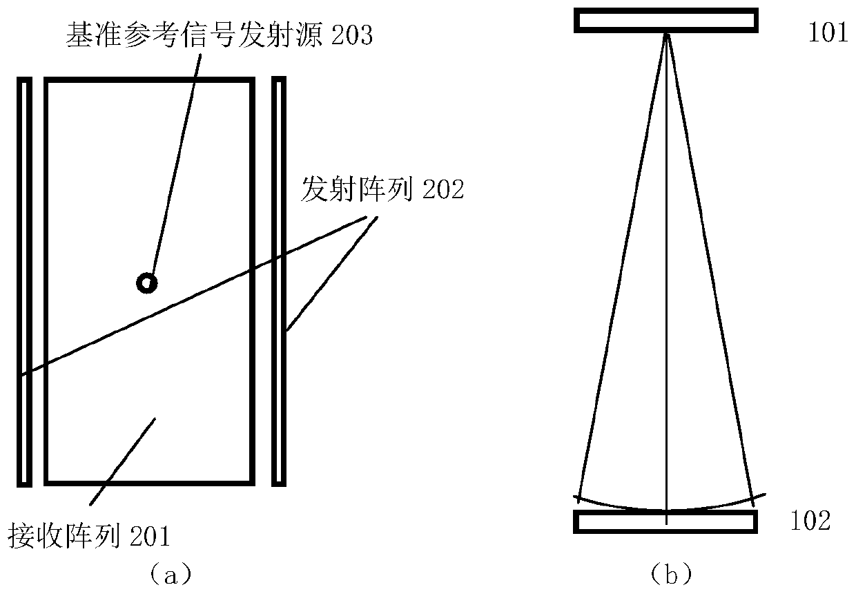
[0032] Each transceiver array in the radio frequency imaging system calibrated in real time is composed of a receiving array 201, a transmitting array 202 and a reference signal transmitting source 203, see figure 2 (a); a transceiver array pair has two relative transceiver arrays, and the receiving array in each transceiver array provi...


PUM


Abstract

The invention discloses a three-dimensional radio frequency imaging system with a real-time calibration. The three-dimensional radio frequency imaging system comprises a plurality of MIMO radio frequency imaging transceiving array pairs. One transmitting-receiving array pair is provided with two opposite transmitting-receiving arrays, and the transmitting source in the other opposite transmitting-receiving array provides a benchmark reference signal for the receiving array in each transmitting-receiving array to complete phase calibration between array units. When the radio frequency imaging system works, the phase of an irradiation signal is taken out as a reference to realize real-time phase calibration according to different irradiation and reflection amplitudes during receiving by utilizing the gap of a target during movement, so that the imaging precision of the radio frequency imaging system is improved, and the bandwidth of the use frequency is reduced.

Description

technical field [0001] The present invention relates to the application of radio frequency phased array or MIMO array, such as radio frequency imaging technology, which mainly focuses on millimeter wave anti-terrorist human security imaging. The radar system can also be regarded as an imaging system, so the present invention is also applicable to radar detection systems. Other radio frequency imaging applications can be robot vision imaging systems, satellite microwave / millimeter wave remote sensing imaging, etc. in any application that requires array receiving and transmitting. [0002] Radio frequency here refers to radio frequencies including UHF / microwave / millimeter wave / terahertz. Background technique [0003] The complete analog RF phased array can only form a single beam, so its receiver has slow speed in search and scan, low signal-to-noise ratio, and short detection distance. Using analog RF phased array single-beam technology for two-dimensional imaging has disad...

Claims


Application Information

Patent Timeline
Patent Type & Authority Applications(China)
IPC IPC(8): G01S13/89G01S7/40
CPCG01S13/89G01S7/40
Inventor 穆丰浩徐立
Owner 徐立
Why Eureka
Try Eureka