Electric control zooming plane lens

A flat lens, electronically controlled zoom technology, applied in nonlinear optics, instruments, optics, etc., can solve problems such as dispersion and fixed focal length, and achieve the effect of high system light energy utilization, enhanced stability, and improved system integration.

Pending Publication Date: 2020-05-05
INST OF FLUID PHYSICS CHINA ACAD OF ENG PHYSICS
View PDF0 Cites 11 Cited by
  • Summary
  • Abstract
  • Description
  • Claims
  • Application Information

AI Technical Summary

Problems solved by technology

Some planar lenses that have been developed so far, such as binary optical planar lenses, Fresnel liquid crystal lenses, and hyperplane lenses based on metamaterials, have bottleneck problems such as fixed focal lengths and serious dispersion problems, and there is still a large gap from practical applications.

Method used


Image

  • Electric control zooming plane lens
  • Electric control zooming plane lens
  • Electric control zooming plane lens

Examples


Embodiment 1

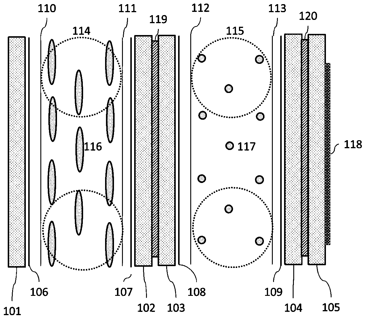
[0031] This embodiment provides an electronically controlled zoom plane lens, such as figure 1 As shown, it includes 5 glass substrates (the first glass substrate 101, the second glass substrate 102, the third glass substrate 103, the fourth glass substrate 104 and the fifth glass substrate 105), 4 transparent conductive layers (the first conductive film layer 106, second conductive film layer 107, third conductive film layer 108 and fourth conductive film layer 109), 4 alignment layers (first alignment layer 110, second alignment layer 111, third alignment layer 112 and fourth alignment layer Alignment layer 113), cell thickness control spacer (first spacer 114 and second spacer 115), liquid crystal layer (first liquid crystal layer 116 and second liquid crystal layer 117) and micro-nano structure layer (micro-nano structure layer 118 ) and glue layers (the first glue layer 119 and the second glue layer 120).

[0032] Among them, the first glass substrate 101, the second gla...

Embodiment 2

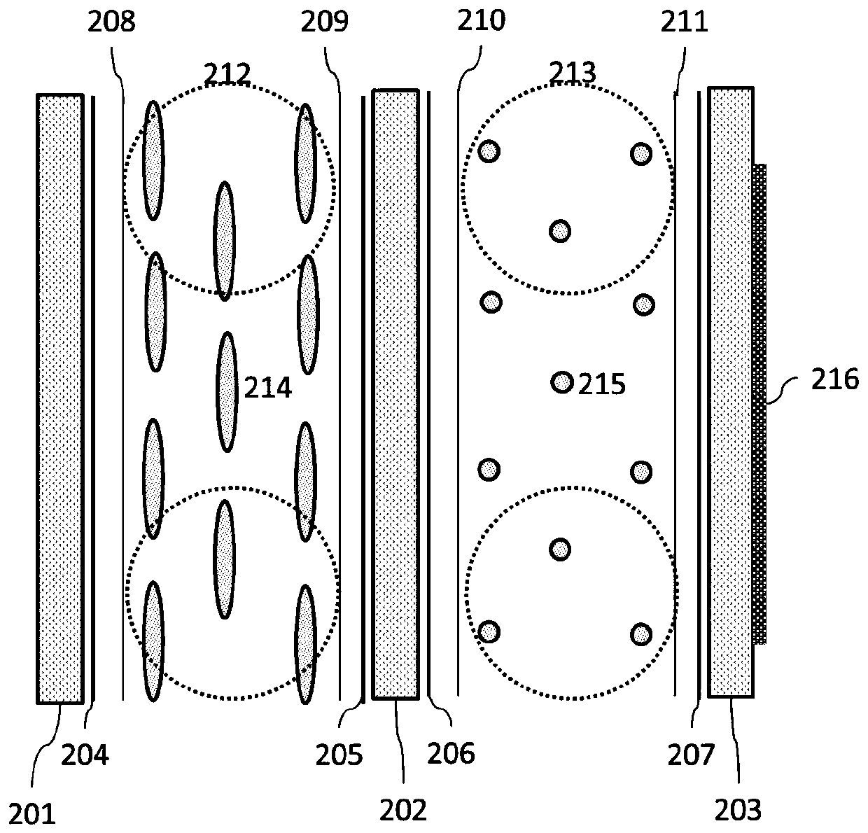
[0037] This embodiment provides an electronically controlled zoom plane lens, such as figure 2 As shown, it includes three glass substrates (the first glass substrate 201, the second glass substrate 202 and the third glass substrate 203), four transparent conductive layers (the first conductive film layer 204, the second conductive film layer 205, the third Conductive film layer 206 and fourth conductive film layer 207), four alignment layers (first alignment layer 208, second alignment layer 209, third alignment layer 210 and fourth alignment layer 211), two cell thickness control spacers (the first spacer 212 and the second spacer 213), two liquid crystal layers (the first liquid crystal layer 214 and the second liquid crystal layer 215) and one micro-nano structure layer (micro-nano structure layer 216). This structure is similar to the structure of the electronically controlled zoom plane lens provided in Example 1, except that in order to reduce the thickness of the lens...

Embodiment 3

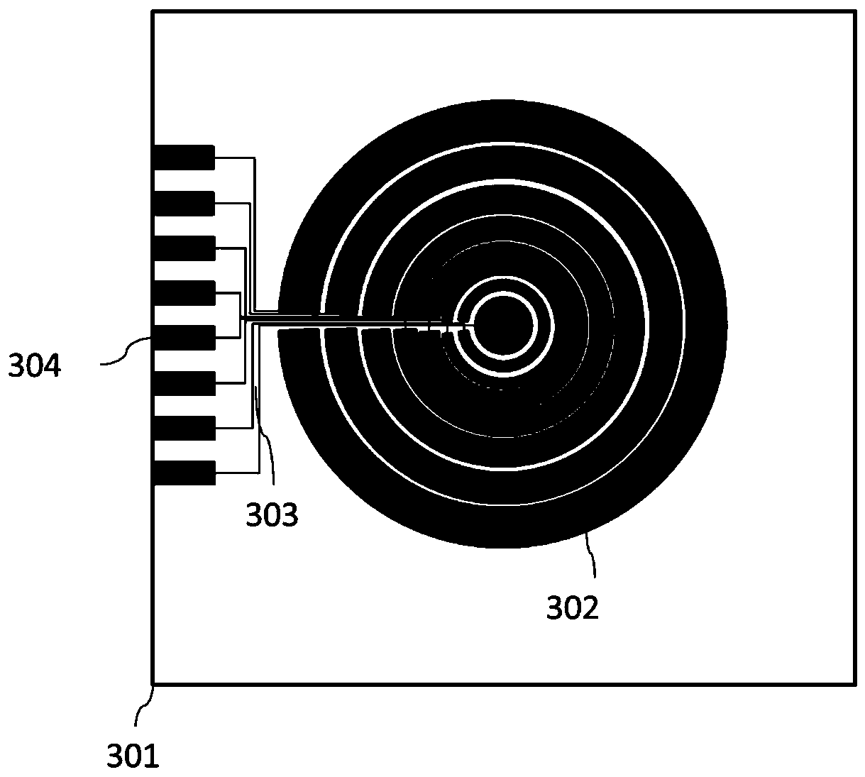
[0039] Further improvement on the basis of Embodiment 1 and Embodiment 2, the independent electrode structure of the liquid crystal lens is as follows image 3 As shown, include a glass substrate 301 (the glass substrate here refers to the first glass substrate 101 and the third glass substrate 103 for embodiment 1); refers to the first glass substrate 201 and the second glass substrate 202 for embodiment 2— side panel), a plurality of concentric diffractive ring electrodes 302 for independent delay control, electrode terminals 304 for connecting the driving circuit, and transparent conductive leads 303 connecting the independent ring electrodes 302 with the electrode terminals 304. The width of the ring electrode 302 is comprehensively designed according to parameters such as the design focal length of the liquid crystal lens, the thickness of the liquid crystal layer, and the birefringence difference. The transparent conductive lead 303 is as thin as possible under the premi...


PUM


Abstract

The invention discloses an electric control zooming plane lens which comprises a first electric control zooming liquid crystal lens, a second electric control zooming liquid crystal lens and a super lens with a fixed focal length which are cascaded. In a state of not applying an electric field, the arrangement direction of molecules in the first liquid crystal layer of the first liquid crystal lens is parallel to the overall mirror surface direction of the first liquid crystal lens, the arrangement direction of the molecules in the second liquid crystal layer of the second liquid crystal lensis parallel to the overall mirror surface direction of the second liquid crystal lens, and the arrangement directions of the molecules in the first liquid crystal layer and the molecules in the secondliquid crystal layer are perpendicular to each other. The electric field is applied to the first liquid crystal layer and the second liquid crystal layer respectively, and the molecular arrangement state of the first liquid crystal layer and the second liquid crystal layer is adjusted by adjusting the electric field intensity. The plane lens is the super lens with a fixed focal length. The planarlens group has an electric control zooming function and is insensitive to polarization based on the combination of the liquid crystal lens and the super lens which are arranged in a cascaded manner,a high-quality imaging effect is achieved and the practical application of the planar lens technology is promoted.

Description

technical field [0001] The invention relates to the field of lens technology, in particular to an electronically controlled zoom plane lens. Background technique [0002] Optical imaging systems are playing an increasingly important role in modern people's daily life and industrial applications, and lenses are an indispensable component, which realizes imaging of targets based on the dispersion or convergence of light. Small and integratable, no mechanical moving parts, and fast zooming features, the planar lens has important application value in simplifying the structure of the optical system, reducing weight, enhancing stability, and improving the level of system intelligence. Some planar lenses that have been developed so far, such as binary optical planar lenses, Fresnel liquid crystal lenses, and hyperplane lenses based on metamaterials, have bottleneck problems such as fixed focal lengths and serious dispersion problems, and there is still a large gap from practical ap...

Claims


Application Information

Patent Timeline
Patent Type & Authority Applications(China)
IPC IPC(8): G02F1/29
CPCG02F1/29G02F1/294
Inventor 沈志学吴欣颐张大勇骆永全赵祥杰黄立贤王海峰刘海涛储松南
Owner INST OF FLUID PHYSICS CHINA ACAD OF ENG PHYSICS
Why Eureka
Try Eureka