Seedling planting device for agricultural machinery

A technology for agricultural machinery and planting seedlings, applied in agriculture, forestry, applications, etc., can solve the problems of poor clamping effect of tree trunks and damage of tree trunks, and achieve good clamping effects, prevent damage, and avoid the effects of trunk sliding

Inactive Publication Date: 2020-05-08
李甲明
View PDF0 Cites 3 Cited by
  • Summary
  • Abstract
  • Description
  • Claims
  • Application Information

AI Technical Summary

Problems solved by technology

[0004] Based on the technical problems that the existing seedling-carrying device has a simple design structure, poor clamping effe

Method used


Image

  • Seedling planting device for agricultural machinery
  • Seedling planting device for agricultural machinery
  • Seedling planting device for agricultural machinery

Examples


Embodiment 1

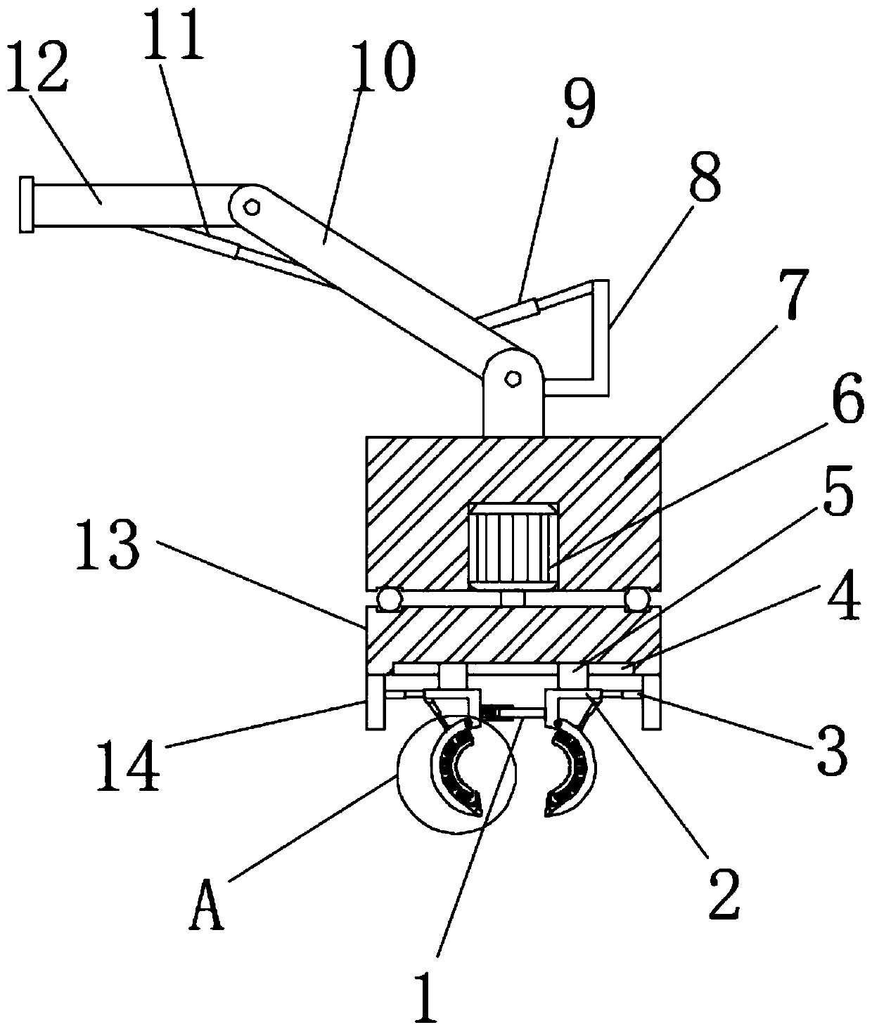
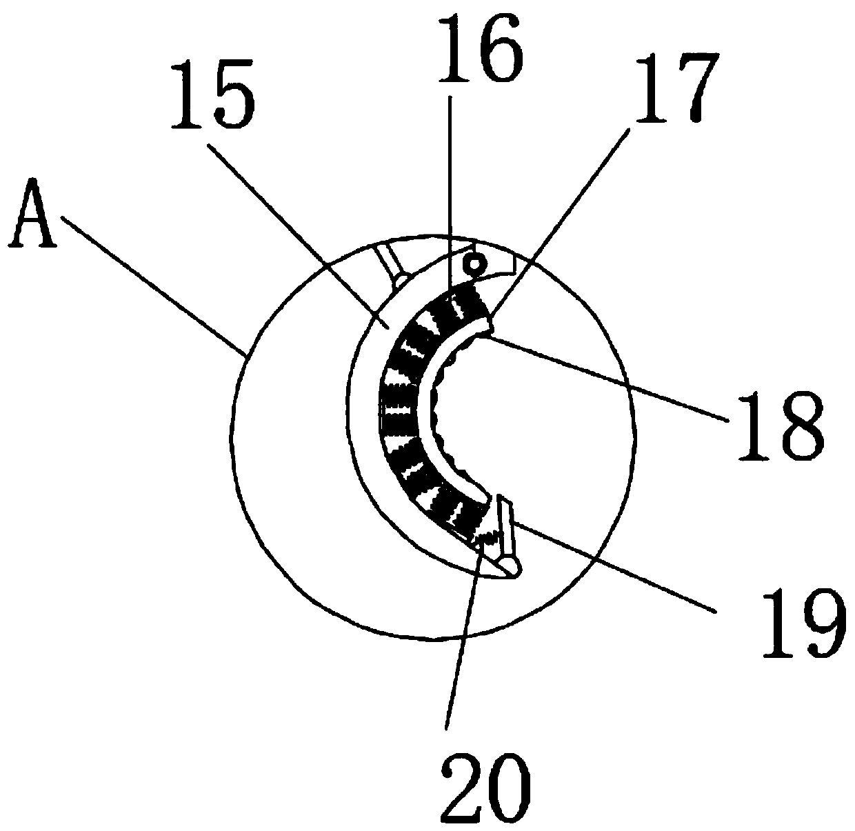
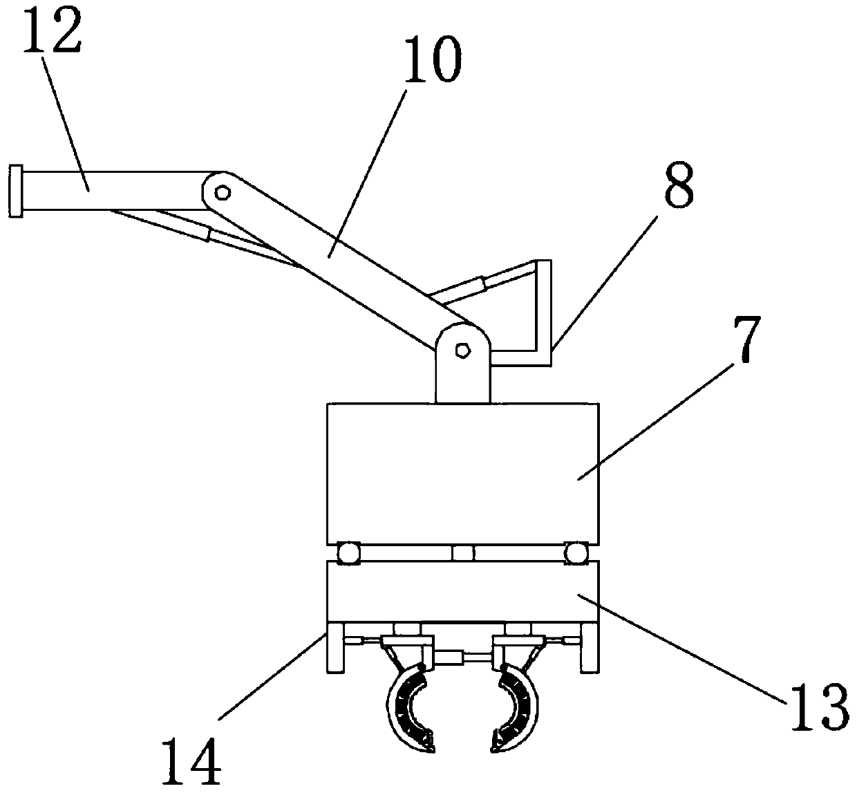
[0028] refer to Figure 1-4 , a seedling planting device for agricultural machinery, comprising a fixed block 7, the outer wall of the bottom of the fixed block 7 is provided with a groove, and the inner wall of the groove is fixed with a rotating motor 6 by screws, and the output shaft of the rotating motor 6 is connected by a coupling There is a rotating plate 13, and both sides of the outer wall at the bottom of the rotating plate 13 are fixed with a fixed plate 14 by screws, and the outer walls on the opposite side of the two fixed plates 14 are fixed with electric telescopic rods 3 by screws, and the electric telescopic rods 3 piston rods One end is fixed with a moving plate 2 by a screw, and the bottom end of the moving plate 2 is connected with a crescent-shaped splint 15 through a hinge, and the inner wall of the splint 15 is provided with a buffer spring 16, and the end of the buffer spring 16 away from the splint 15 is fixed with a clamp by a screw. ring 17, and the ...

Embodiment 2

[0038] refer to Figure 1-5, a seedling planting device for agricultural machinery, including a guide cylinder 21 fixed to the outer wall of one of the moving plates 2 by screws, and a return spring 22 is arranged on the inner wall of the guide cylinder 21, and an end of the return spring 22 far away from the guide cylinder 21 is connected with a squeeze Pressing plate 24, the outer wall of another moving plate 2 is provided with guide bar 1, and one end of guide bar 1 is provided with the extruding block 23 that section is trapezoidal structure, and extruding block 23 forms sliding fit with the inner wall of guide tube 21.

[0039] During use, during the relative movement of the two splints 15, the extruding block 23 can enter into the guide cylinder 21. Since the cross section of the extruding block 23 is an isosceles trapezoidal structure, it is very convenient to enter into the guide cylinder 21 and extrude. After the block 23 enters the guide tube 21, a connection can be ...


PUM


Abstract

The invention belongs to the technical field of seedling planting devices, and especially relates to a seedling planting device for agricultural machinery. For the problems of simple design structureof existing seedling planting devices, poor trunk clamping effects and easy damage to trunks, the following schemes are provided: the device includes a fixing block; the outer wall at the bottom of the fixing block is provided with a groove; a rotary motor is fixed on the inner wall of the groove through a screw; the output shaft of the rotary motor is connected to a rotating plate through a coupling; fixing plates are fixed on the two sides of the outer wall at the bottom of the rotating plate; electric telescoping rods are fixed on outer walls of the opposite sides of the two fixing plates through the screws; and moving plates are fixed on one ends of piston rods of the electric telescoping rods. The occurrence of trunk sliding can be avoided; buffer springs can achieve good buffering effects, so that damages to the trunks caused by excessive clamping force during clamping can be prevented; and the device is good in clamping effect, so that transplanting quality of saplings can be guaranteed, and the survival rate of the saplings can be increased.

Description

technical field [0001] The invention relates to the technical field of seedling loading devices, in particular to a seedling planting device for agricultural machinery. Background technique [0002] Agriculture refers to an important industrial sector in the national economy. It is a sector that takes land resources as its production object. It is an industry that produces food and industrial raw materials by cultivating animal and plant products. Agriculture belongs to the primary industry. The sector that uses land resources for planting and production is the planting industry. The sector that uses the water space on the land for aquaculture is aquaculture, also known as fishery. The sector that uses land resources to cultivate and harvest forests is forestry, which uses land resources to cultivate or directly use grassland for development. Animal husbandry is animal husbandry. The small-scale processing or production of these products is a sideline, and they are an inte...

Claims


Application Information

Patent Timeline
IPC IPC(8): A01G23/04
CPCA01G23/04
Inventor 孙玲玲王家孟李甲明
Owner 李甲明
Why Eureka
Try Eureka