Single crystal furnace dedusting and filtering system

A filter system and single crystal furnace technology, applied in the direction of dispersed particle filtration, dispersed particle separation, chemical instruments and methods, etc., can solve the problems of affecting dust removal effect, exhaust pipe blockage, difficult to remove, etc.

Inactive Publication Date: 2020-05-08
XIAN ESWIN MATERIAL TECH CO LTD +1
View PDF2 Cites 3 Cited by
  • Summary
  • Abstract
  • Description
  • Claims
  • Application Information

AI Technical Summary

Problems solved by technology

[0003] However, the filter unit 3 inside the existing single crystal furnace dust removal system is mostly a filter tube type with weak permeability and small filter area; on the other hand, in the initial preparation stage of the crystal pulling furnace 2, due to the The pressure of the dust removal tank is lower than the pressure inside the main body 1 of the dust removal tank, and the phenomenon of gas sucking back is prone to occur, so that the gas inside the main body of the dust removal tank 1 enters the inside of the crystal pulling furnace 2, and the cleanliness of the furnace is very seriously affected after the back sucking, especially when feeding and vacuumizing stage, if there is back suction, the polysilicon material in the crystal pulling furnace 2 will not be usable, if not found, the single crystal rate and single crystal quality of the generated crystal bar will be affected due to excessive impurity content in the crystal pulling process
In addition, since the oxides and other impurity particles generated by crystal pulling during the dust removal process will accumulate at the bottom of the main body 1 of the dust removal tank, it is difficult to remove them after the crystal pulling is completed, which will cause the exhaust pipe to be blocked, thereby affecting the dust removal effect

Method used


Image

  • Single crystal furnace dedusting and filtering system
  • Single crystal furnace dedusting and filtering system
  • Single crystal furnace dedusting and filtering system

Examples


Embodiment 1

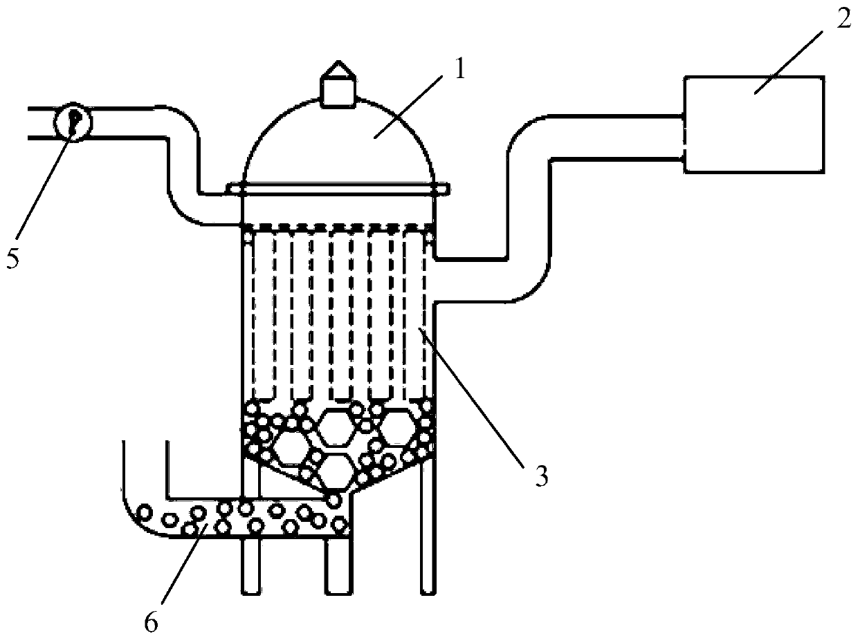
[0036] See figure 2 , figure 2 It is a schematic structural diagram of a single crystal furnace dust removal and filtration system provided by an embodiment of the present invention. The single crystal furnace dust removal filtration system includes a dust removal tank main body 1 and a vacuum pump assembly, wherein the dust removal tank main body 1 is in communication with the single crystal furnace 2, and the dust removal tank main body 1 is provided with a filter unit 3 inside; the vacuum pump assembly includes a vacuum pipeline 4 and a set The vacuum pump 5 on the vacuum pipeline 4 and the vacuum pipeline 4 communicate with the main body 1 of the dust removal tank. The vacuum pump assembly is used to vacuum the inner cavity of the dust removal tank body 1 when the single crystal furnace 2 is pulling crystals, so as to remove the impurity gas inside the single crystal furnace 2, and to clean the dust removal tank body 1 when the single crystal furnace 2 finishes crystal pul...

Embodiment 2

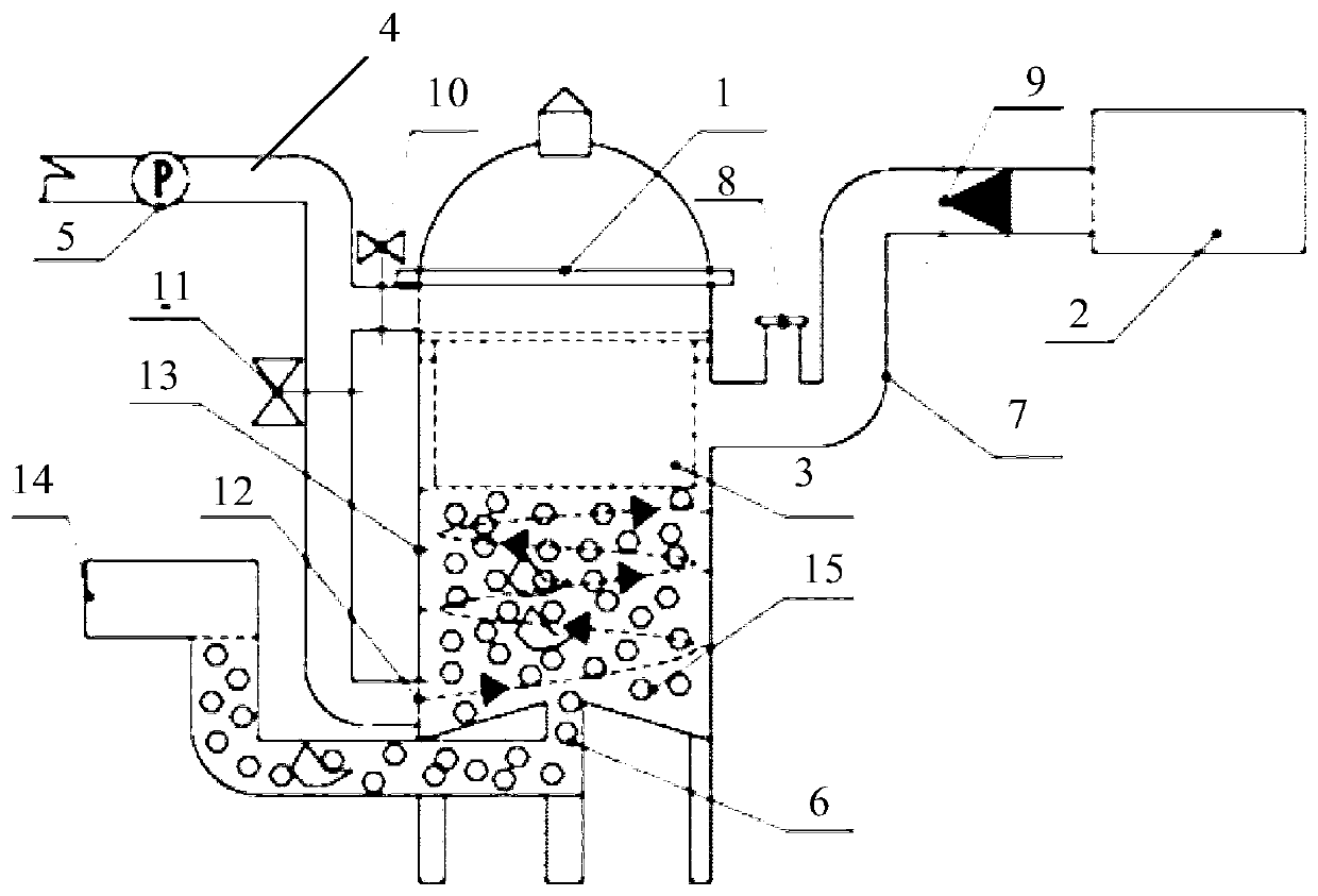
[0049] On the basis of the foregoing embodiment, this embodiment provides another single crystal furnace dust removal and filtration system. See Figure 7 , Figure 7 It is a schematic structural diagram of another single crystal furnace dust filter system provided by an embodiment of the present invention. The single crystal furnace dust removal and filtration system of this embodiment includes a vacuum pump assembly and two parallel dust removal tank main bodies 1, wherein each dust removal tank main body 1 is connected to a different single crystal furnace, and each dust removal tank main body 1 is provided with a filter inside. Unit, each dust removal tank body 1 is used for dust removal and filtration of a separate single crystal furnace. The vacuum pump assembly of this embodiment includes a vacuum pipe 4 and a vacuum pump 5 arranged on the vacuum pipe 4, and the vacuum pipe 4 is in communication with two dust removal tank bodies 1 at the same time. Similarly, the vacu...


PUM


Abstract

The invention discloses a single crystal furnace dedusting and filtering system. The system comprises a dedusting tank main body and a vacuum pump assembly, and the dedusting tank main body is communicated with a single crystal furnace, and a filtering unit is arranged in the dedusting tank main body so as to filter a gas discharged by the single crystal furnace; a discharge port for discharging impurity particles is formed in the lower end of the dust removal tank main body; the vacuum pump assembly comprises a vacuumizing pipeline and a vacuum pump arranged on the vacuumizing pipeline; and the vacuumizing pipeline is communicated with the dust removal tank main body, and the vacuum pump assembly is used for vacuumizing the inner cavity of the dust removal tank main body when the single crystal furnace carries out crystal pulling and air blowing air on the inner cavity of the dust removal tank main body when the single crystal furnace finishes crystal pulling. The dedusting and filtering system can effectively discharge impurity particles such as oxide deposited at the bottoms of the filtering unit and the tank man body, prevent the exhaust pipeline from being blocked and improvethe dust removal effect.

Description

Technical field [0001] The invention relates to the technical field of wafer manufacturing, and more specifically, to a single crystal furnace dust removal and filtration system. Background technique [0002] When single crystal grows, vacuum requirements are high, so each single crystal furnace is equipped with an independent vacuum pump to vacuum. See figure 1 , figure 1 It is a schematic structural diagram of an existing single crystal furnace dust removal system. The single crystal furnace dust removal system has a simple structure, including a dust removal tank body 1 and a vacuum pump 5 that are connected to each other. The bottom of the dust removal tank body 1 is a material accumulation area. During the single crystal pulling process of the crystal pulling furnace 2, the vacuum pump 5 continuously moves The gas in the crystal pulling furnace 2 is extracted outside, and impurities such as gas are discharged from the discharge port 6. [0003] However, the filtering unit 3 ...

Claims


Application Information

Patent Timeline
IPC IPC(8): B01D46/00B01D46/48
CPCB01D46/0008B01D46/48B01D46/90
Inventor 潘浩
Owner XIAN ESWIN MATERIAL TECH CO LTD
Why Eureka
Try Eureka