Electroplated steel wire tooth splice type cup-shaped abrasive wheel

A technology of cup-shaped grinding wheel and steel wire, applied in the direction of bonded grinding wheel, abrasive material, metal processing equipment, etc., can solve the problems of high processing cost, high grinding heat, short overall life, etc., and achieve cooling and rapid chip removal, The effect of refurbishment cost reduction

Pending Publication Date: 2020-05-08
宋京新 +1
View PDF0 Cites 1 Cited by
  • Summary
  • Abstract
  • Description
  • Claims
  • Application Information

AI Technical Summary

Problems solved by technology

The above method has poor cooling and chip removal effects, high grinding heat, and easily causes coating burns and delamination. It is difficult for the grinding wheel to adapt to high-speed and efficient processing, and the life of the grinding wheel is short.
[0003] At present, because the electroplated grinding wheel is a single layer of diamond, the overall service life is short. If the optimal use is made of a water tank that is intensively processed on the substrate, the machining cost will be too high, and the short service life will result in extremely low cost performance; Diamond, the process is complex, the manufacturing cost is high and difficult

Method used


Image

  • Electroplated steel wire tooth splice type cup-shaped abrasive wheel
  • Electroplated steel wire tooth splice type cup-shaped abrasive wheel
  • Electroplated steel wire tooth splice type cup-shaped abrasive wheel

Examples


Embodiment Construction

[0042] The principles and features of the present invention are described below in conjunction with the accompanying drawings, and the examples given are only used to explain the present invention, and are not intended to limit the scope of the present invention.

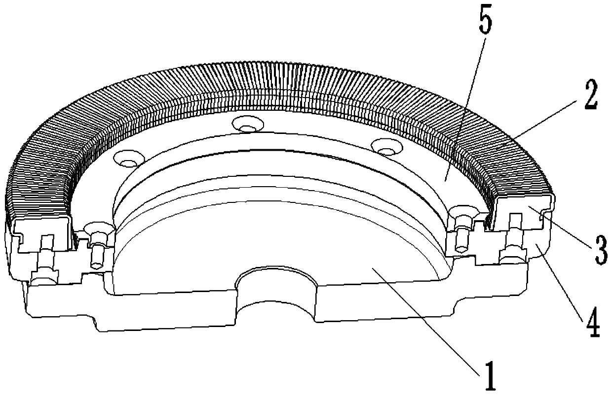
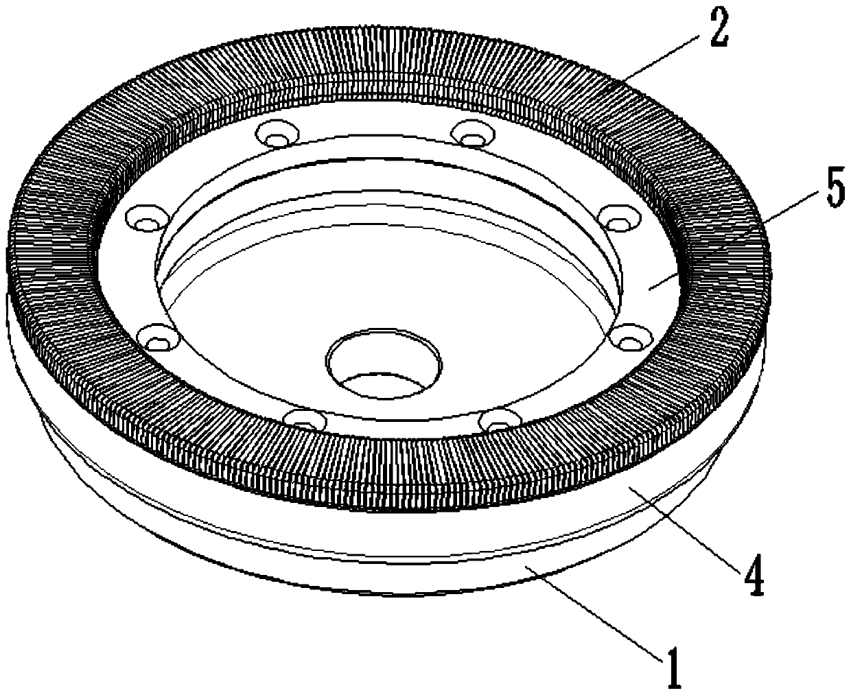
[0043] Such as figure 1 , 2As shown, an electroplated steel wire tooth split type cup-shaped grinding wheel includes a first base 1 for connecting external equipment, several steel wire teeth 2, a support ring 3 for supporting the several steel wire teeth 2, and a The support ring 3 is fixed on the second base body 4 on the first base body 1 and the clamping part 5 for clamping the wire teeth 2, and the second base body 4 is stacked on one side of the first base body 1 Above, the clamping part 5 and the support ring 3 are arranged side by side on the second substrate 4, and the several steel wire teeth 2 are arranged on the support ring 3, and the outer wall is coated with diamond to form grinding surface, and one...


PUM

PropertyMeasurementUnit
thicknessaaaaaaaaaa

Abstract

The invention relates to an electroplated steel wire tooth splice type cup-shaped abrasive wheel. The abrasive wheel comprises a first matrix, a plurality of steel wire teeth, a supporting ring for supporting the steel wire teeth, a second matrix used to fix the supporting ring to the first matrix, and a clamping portion used to tightly clamp the steel wire teeth. The second matrix is axially arranged on the first matrix in a stacking manner. The clamping portion and the supporting ring are arranged on the second matrix in parallel. Diamond is plated on the outer walls of the steel wire teeth.The steel wire teeth are arranged on the supporting ring to form a grinding surface. One end of each steel wire tooth is arranged in a seam between the clamping portion and the supporting ring in a clamped manner. The steel wire teeth are assembled on the supporting ring in a mechanical splice manner. The matrixes are reusable tools which can be used repeatedly; the grinding surface formed by splicing the steel wire teeth are convenient to replace, and therefore, the renovation cost of the abrasive wheel is greatly reduced; and according to the cup-shaped abrasive wheel formed by splicing thesteel wire teeth, an axial working face is formed, a water feeding channel is formed between every two adjacent teeth, and it is beneficial for cooling and quick scrap removal.

Description

technical field [0001] The invention relates to the technical field of grinding wheel tools, in particular to an electroplated steel wire tooth split type cup-shaped grinding wheel. Background technique [0002] At present, the electroplated grinding wheel usually adopts the external cooling method. The specific structure is as follows: processing a few water channels on the substrate, or shielding several strip-shaped areas without diamond plating to form water channels. When the grinding wheel is working, a small amount of water is brought in by the rotation of the grinding wheel in its grinding work area (the area where the grinding wheel and the workpiece are in contact) for cooling. The chip space is the narrow space formed between the diamond exposure and the coating. The above method has poor cooling and chip removal effects and high grinding heat, which can easily cause coating burns and delamination. It is difficult for the grinding wheel to adapt to high-speed an...

Claims


Application Information

Patent Timeline
Patent Type & Authority Applications(China)
IPC IPC(8): B24D7/18B24D7/10B24D7/16
CPCB24D7/10B24D7/16B24D7/18
Inventor 宋京新龙慧玲叶勇赵亮王志勇秦凤明杨光亚
Owner 宋京新
Why Eureka
Try Eureka