Method of manufacturing glass preforms for optical fibers
A technology for preforms and optical fibers, which is applied in the field of manufacturing silica-based glass preforms, glass core preforms, and optical fibers including fluorine-doped regions, can solve the problems of surface corrosion of quartz glass, formation of pits in muffle tubes, and tube formation. Problems such as wall thickness reduction
- Summary
- Abstract
- Description
- Claims
- Application Information
AI Technical Summary
Problems solved by technology
Method used
Image
Examples
example 1
[0127] Example 1 (comparison)
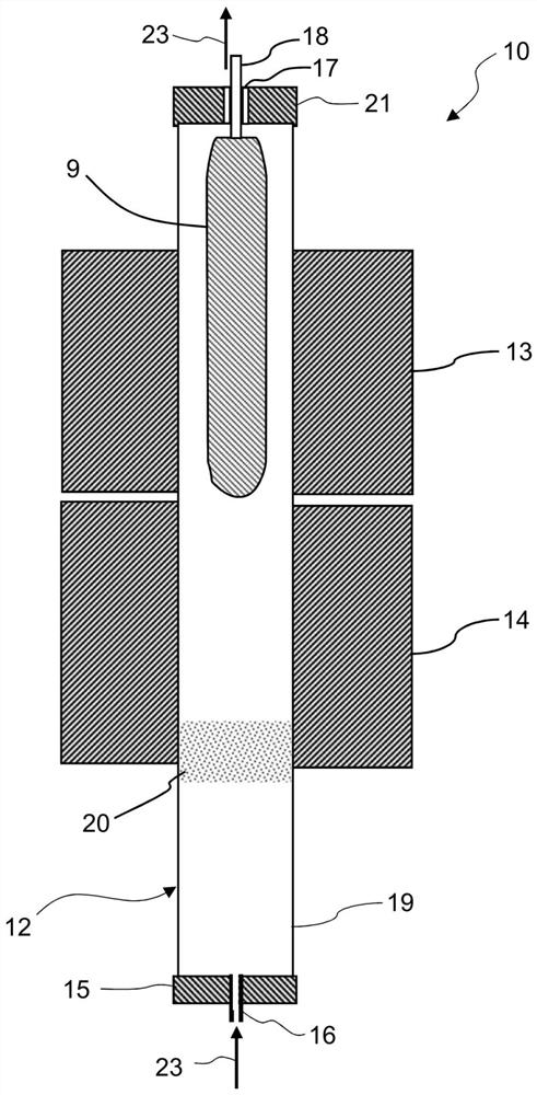
[0128] Insert the soot core preform into the reference Figure 4 Described in the type of dehydration consolidation furnace. Simultaneous dehydration and fluorine doping stages were performed by placing the preform in the upper hot zone set at 1000-1100 °C, while the lower hot zone was set at 1450 °C. The soot core preform was held in the upper hot zone for 1.5 hours while rotating at 5 rpm and exposed to 80 L / min of helium + 1.5 L / min of chlorine + 0.3 L / min of SF 6 in the atmosphere of the mixed gas flow.
[0129] The dehydrated and fluorine-doped soot core preform was then driven downward at a speed of 4 mm / min towards the lower hot zone of the furnace set at a temperature of 1550°C while in a flow of 20 L / min of helium at 1 rev / min The speed is rotated until the entire preform passes through the lower hot zone for consolidation. At the beginning of the descent towards the lower hot zone, a vacuum is created in the central longitudinal ho...
example 2
[0133] Example 2 (comparison)
[0134] Insert the soot core preform into the reference Figure 4 Described in the type of dehydration consolidation furnace. As in Example 1, the dehydration and fluorine doping stages were performed simultaneously, and then the central longitudinal pores were consolidated and closed simultaneously, except that the treatment time for the simultaneous dehydration and fluorine doping stages was 4.5 hours.
[0135] The average value of optical attenuation is the same as in Example 1.
[0136] Image 6 The measured refractive index profiles of the grooved regions of the mandrels produced according to this example are shown. The longer processing time combined with fluorine doping and dehydration resulted in wider trench regions near the cladding layer.
[0137] Even more pronounced pit formation was observed on the muffle due to the 3 times the doping stage as in Example 1.
example 3
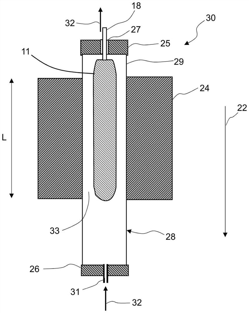
[0139] Insert soot core preforms such as figure 2 In the first muffle of a first furnace of the type shown with a single hot zone. The fluorine doping stage is carried out by placing the soot core preform in a single hot zone set to a temperature of 1000°C. The soot core preform was kept in this single hot zone for a doping time of 1 hour while rotating at 5 rpm and exposed to helium flowing at a flow rate of 20 L / min and a flow rate of 0.3 L / min SF 6 in the atmosphere. then stop sf 6 flow, and the preform was kept in the furnace muffle for 1 hour to vent fluorine-containing gas.
[0140] Subsequently, the fluorine-doped soot preform is removed from the first furnace and inserted into the second muffle of the second furnace, which is Figure 4 A standard dehydration consolidation furnace of the type shown. The second furnace was the same furnace used in the comparative example, but fitted with a new quartz muffle.
[0141] The dehydration stage was carried out by placi...
PUM
| Property | Measurement | Unit |
|---|---|---|
| diameter | aaaaa | aaaaa |
Abstract
Description
Claims
Application Information
 - R&D
- Intellectual Property
- Life Sciences
- Materials
- Tech Scout
- Unparalleled Data Quality
- Higher Quality Content
- 60% Fewer Hallucinations
Browse by: Latest US Patents, China's latest patents, Technical Efficacy Thesaurus, Application Domain, Technology Topic, Popular Technical Reports.
© 2025 PatSnap. All rights reserved.Legal|Privacy policy|Modern Slavery Act Transparency Statement|Sitemap|About US| Contact US: help@patsnap.com


