A transfer and unloading method for the secondary lining steel bars of small-diameter tunnels

A small-diameter, steel-reinforced technology, used in tunnel linings, tunnels, shaft linings, etc., can solve the problems of low manual operation efficiency, large secondary handling volume, and high safety risks, and achieve low manual operation intensity and less manual use. , the effect of high degree of mechanization

Active Publication Date: 2021-06-08
CCTEB INFRASTRUCTURE CONSTR CO LTD +1
View PDF5 Cites 0 Cited by
  • Summary
  • Abstract
  • Description
  • Claims
  • Application Information

AI Technical Summary

Problems solved by technology

[0002] The diameter of the conventional tunnel is relatively large, and the transportation and unloading of steel bars required in the tunnel can be carried out manually with small vehicles or conventional cranes. The working space is large and the operation is convenient for personnel.
For small-diameter full-circle tunnels with a diameter of less than 4m, small vehicles and conventional cranes cannot walk. At the same time, due to the narrow tunnel space, low manual operation efficiency and high safety risks, conventional steel bar transfer and unloading methods are not suitable for small-diameter tunnels.
[0003] The transportation distance of the secondary lining steel bar is long, and the total transportation volume is large. The material transportation is carried out by handcarts and manual methods, which cannot meet the requirements of work efficiency.
Moreover, after the secondary lining steel bars enter the tunnel, in order to facilitate subsequent steel bar binding, the steel bars need to be distributed and placed in the tunnel in a certain order. Therefore, after the steel bars are transported to the unloading area, there is still a huge amount of secondary handling, and the bundled steel bars are heavy. , relying only on manual handling does not meet actual needs

Method used


Image

  • A transfer and unloading method for the secondary lining steel bars of small-diameter tunnels
  • A transfer and unloading method for the secondary lining steel bars of small-diameter tunnels
  • A transfer and unloading method for the secondary lining steel bars of small-diameter tunnels

Examples


Embodiment Construction

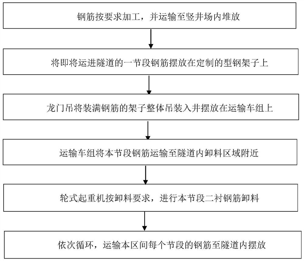
[0028] Such as figure 1 As shown, it is a schematic flow diagram of steel bar transfer and unloading method in a small-diameter tunnel of the present invention, which mainly includes the following construction steps:

[0029] Step 1: According to the design and binding requirements of the second-lined steel bars of the tunnel, all the second-lined steel bars in this project will be processed and unloaded in the steel bar processing plant by division, type, and size. Segment arc steel bar. After the steel bars are processed, they are bundled into small bundles according to the demand of a single segment. After each bundle is processed, they are marked with post-it notes and stacked in sections. After the tunnel is penetrated, the steel bars are transported to the shaft yard by a trailer for sorting and stacking.

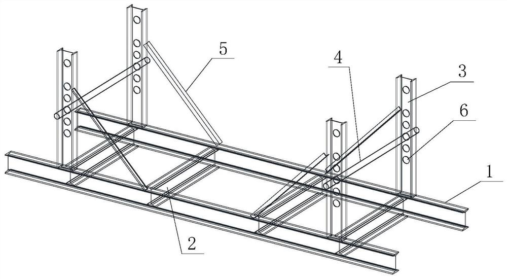
[0030] Step 2: Divide the tunnel section into a single section with a length of 43.2m, and transport steel bars in sequence according to the section division. Custo...


PUM


Abstract

The invention discloses a method for transferring and discharging steel bars for secondary linings of small-diameter tunnels. Place them on the customized profiled steel racks in sequence, then hoist the aforementioned profiled steel racks to the flatbed truck of the transport vehicle group at the bottom of the shaft, and transport the steel bars of this segment to the unloading area of ​​the corresponding segment in the tunnel by the transport vehicle group. Use a custom-made wheeled crane to lift the steel bars of this section from the steel frame on the transport vehicle to the unloading area in turn according to the requirements of the steel bar binding sequence, and repeat the above steps to complete the transportation and stacking of the secondary lining steel bars in the tunnel area. Aiming at the situation where the space of small-diameter tunnels is limited and the conventional unloading equipment cannot be used, the invention realizes the rapid transfer and unloading of steel bars, greatly improves the transportation efficiency of steel bars, has simple operation and high degree of mechanization, and effectively reduces the labor intensity of operators. .

Description

technical field [0001] The invention belongs to the technical field of tunnel construction, and in particular relates to a method for transferring and unloading steel bars used for the second lining of small-diameter tunnels. Background technique [0002] Conventional tunnels have a large diameter, and the transportation and unloading of steel bars required in the tunnel can be carried out manually with small vehicles or conventional cranes. The work space is large and the operation is convenient for personnel. For small-diameter full-circle tunnels with a diameter of less than 4m, small vehicles and conventional cranes cannot walk. At the same time, due to the small tunnel space, low manual operation efficiency and high safety risks, conventional steel bar transfer and unloading methods are not suitable for small-diameter tunnels. [0003] The transportation distance of the second lining steel bar is long and the total transportation volume is large. The material transporta...

Claims


Application Information

Patent Timeline
Patent Type & Authority Patents(China)
IPC IPC(8): E21D11/40
CPCE21D11/40
Inventor 杨庭友余南山刘开扬蒋尚志贾瑞华刘其成石九州刘灿光柯林鲁翔翔
Owner CCTEB INFRASTRUCTURE CONSTR CO LTD
Why Eureka
Try Eureka