
Autonomous underwater electromagnetic signal measuring device and measuring method

A technology of electromagnetic signal and measuring device, applied in the direction of measuring device, measuring electrical variables, electromagnetic field characteristics, etc., can solve problems such as difficulty in finding a suitable work boat, inability to monitor at a longer distance, and unable to find measurement work in the distant sea, etc. Achieve the effect of avoiding invalid data or even not starting work, reducing the height of the boom, and reducing the overall height

Inactive Publication Date: 2020-05-08
中国电波传播研究所
View PDF7 Cites 4 Cited by
  • Summary
  • Abstract
  • Description
  • Claims
  • Application Information

AI Technical Summary

Problems solved by technology

[0004] This kind of submersible buoy device has the following disadvantages: work on the bottom, each device can only measure one receiving point at a time, and when measuring a large-scale sea area, it is necessary to deploy multiple devices or recover one device multiple times and delivery, the workload is huge
But this device also has the following disadvantages: the delivery is complicated
This puts extremely high demands on both the wharf and the workboat, especially the difficulty in finding a suitable workboat. Many offshore surveys have to be canceled simply because no suitable workboat can be found.
Transition measurement test is complex
For each transition measurement, it is necessary to use a ship to recover and release the equipment once, which is time-consuming and labor-intensive
The communication distance between the measurement and control terminal and the buoy is only a few kilometers, and it is impossible to achieve longer-distance monitoring

Method used


Image

  • Autonomous underwater electromagnetic signal measuring device and measuring method
  • Autonomous underwater electromagnetic signal measuring device and measuring method
  • Autonomous underwater electromagnetic signal measuring device and measuring method

Examples


Embodiment 1

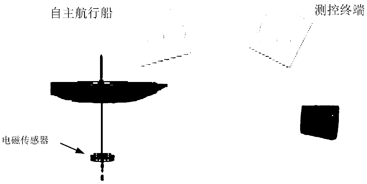
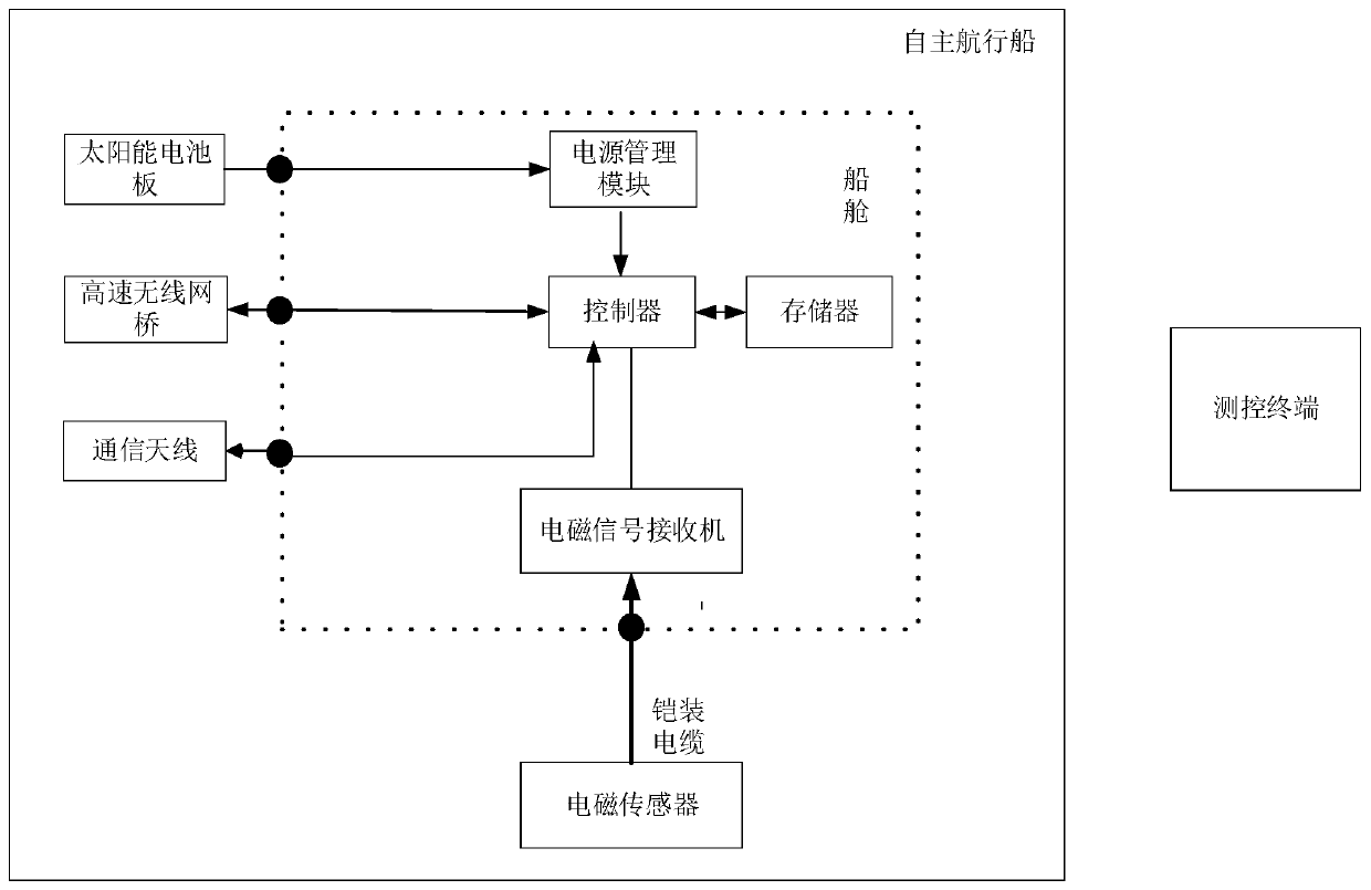
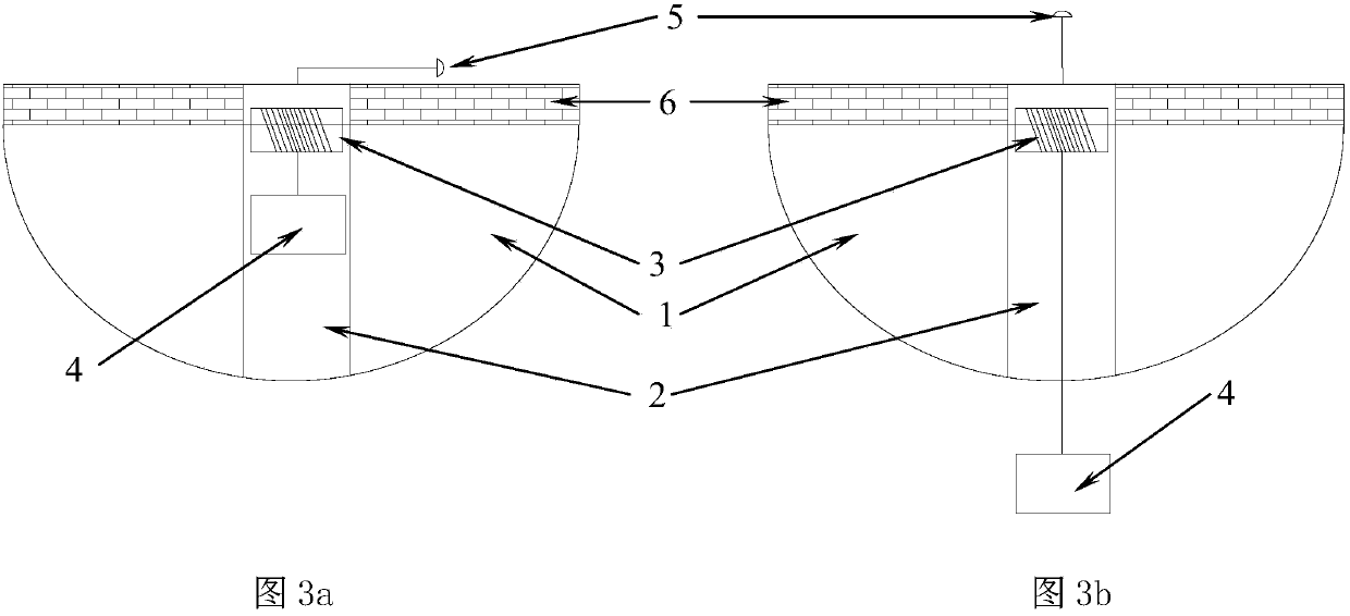
[0035] Embodiment 1, this embodiment discloses an autonomous underwater electromagnetic signal measurement device, such as figure 1 As shown, including the self-navigating ship and the measurement and control terminal, the communication antenna 5 is installed on the deck of the self-navigating ship and the solar panel 6 is laid, as Figure 3a As shown, a moon pool 2 communicating with the outside of the ship bottom is provided on the hull 1, a winch 3 winding an armored cable is installed in the moon pool, and an electromagnetic sensor 4 is suspended on the armored cable, as figure 2 As shown, a controller is installed in the cabin, the controller is electrically connected to the solar panel through the power management module, and is electrically connected to the electromagnetic sensor through the electromagnetic signal receiver. In addition, the controller is also connected to the high-speed wireless network bridge, the communication antenna and the memory It is electricall...


PUM


Abstract

The invention discloses an autonomous underwater electromagnetic signal measuring device and measuring method. The system comprises an autonomous navigation ship and a measurement and control terminal. A communication antenna is installed on a deck of the autonomous navigation ship, solar cell panels are laid on the deck. A moon pool communicated with the outside of the bottom of the ship is arranged on a ship body, a winch wound with an armored cable is installed in the moon pool, and an electromagnetic sensor is hung on the armored cable; a controller is installed in a cabin, and the controller is electrically connected with the solar cell panels through a power management module. The measuring device disclosed by the invention has an autonomous navigation function, so that the measuringdevice does not need to be recovered or dragged during transition in transferring; and the autonomous navigation ship is transferrd to a next measuring field only by sending an instruction to the autonomous navigation ship.

Description

technical field [0001] The invention belongs to the field of underwater detection, in particular to an autonomous underwater electromagnetic environment noise and electromagnetic signal measurement device and measurement method in the field. Background technique [0002] At present, the equipment and measurement methods for underwater electromagnetic signal measurement can be divided into two categories. One is a bottom-mounted device equipped with electrodes and magnetic rods. The device moored under the buoy is towed by the survey ship to the survey point or loaded to the survey point and released for fixed-point survey. [0003] Patent application 200610080789.1 discloses "a submarine plane wave electromagnetic field detection device and measurement method". This device is an ocean submersible buoy, including buoyancy components, lifting components, sound-activated release components, gravity traction components, safety protection components, and signal detection componen...

Claims


Application Information

Patent Timeline
Patent Type & Authority Applications(China)
IPC IPC(8): G01R29/08B63B35/00B63C11/34
CPCB63B35/00B63B2035/007B63C11/34G01R29/0871
Inventor 刘菊彭怀云张红旗李清亮韩逍菲张世田陈宇毛云志王辛刘凯王元新
Owner 中国电波传播研究所
Learn More