Battery system, vehicle system, and battery system heating control method

A battery system and heating film technology, applied in battery/fuel cell control devices, battery temperature control, electric vehicles, etc., can solve problems such as low heating power, inconsistent temperature, and increased temperature difference

Active Publication Date: 2020-10-27
EVE ENERGY CO LTD +1
View PDF10 Cites 0 Cited by
  • Summary
  • Abstract
  • Description
  • Claims
  • Application Information

AI Technical Summary

Problems solved by technology

[0002] The types of heating films currently used in battery modules include: the heating material is copper wire or nickel wire, or a PTC (Positive Temperature Coefficien, positive temperature coefficient) heater. This type of PTC heater has the following problems: PTC can be lowered according to its own temperature. Power, so as to stabilize at a set temperature, but after the design is completed, the heating power curve of each block is also determined, and the temperature difference caused by other factors between different modules cannot be eliminated, and the temperature difference will even be further increased; And multiple PTC heaters are connected in series. When using the total voltage of the battery system to heat all the battery modules in the system, the temperature of the battery modules is not balanced when the system is affected by the environment, so the temperatures of the multiple PTC heaters are not completely consistent. , because each PTC heater is connected in series, the current passing through each PTC heater is consistent, so the low temperature PTC heater has a small resistance, and its heating power is relatively low, while the high temperature PTC heater has a relatively high temperature, its resistance It is also relatively high, resulting in high heating power, and finally leads to inconsistent heating power of each module, and the temperature difference is further widened, so under the influence of the initial temperature difference, the temperature difference is getting larger and larger

Method used


Image

  • Battery system, vehicle system, and battery system heating control method
  • Battery system, vehicle system, and battery system heating control method
  • Battery system, vehicle system, and battery system heating control method

Examples


Embodiment Construction

[0019] The present invention will be further described in detail below in conjunction with the accompanying drawings and embodiments. It should be understood that the specific embodiments described here are only used to explain the present invention, but not to limit the present invention. In addition, it should be noted that, for the convenience of description, only some structures related to the present invention are shown in the drawings but not all structures.

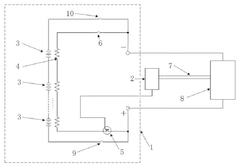
[0020] figure 1 It is a schematic circuit diagram of a battery system provided by an embodiment of the present invention. The battery system is equipped with a heating film, so that the battery system can perform self-heating based on the internally configured heating film when in use. Such as figure 1 As shown, the battery system 1 includes: at least one battery module 3, at least one controllable switch and at least one heating film 4, wherein,

[0021] The first connection end of the heating film 4 is connect...


PUM


Abstract

The embodiment of the invention discloses a battery system, a vehicle system and a battery system heating control method. The battery system comprises at least one battery module, at least one controllable switch and at least one heating film, the first connecting end of the at least one heating film is connected with the high-voltage end of the battery system, and the second connecting end of theat least one heating film is connected with the low-voltage end of the battery system; the at least one heating film is a negative temperature coefficient type heating film and is used for heating the battery module; the at least one controllable switch is arranged between the first connecting end and the high-voltage end and / or between the second connecting end and the low-voltage end, the control end of the controllable switch is connected with the control unit of the battery system, and the controllable switch is used for responding to the control on or off of the control unit. The negative temperature coefficient type heating film is arranged in the battery system, so that the heating film outputs adjustable heating power, uniform temperature heating of each battery module in the battery system is realized, and the temperature of each battery module tends to be consistent while the temperature rises.

Description

technical field [0001] Embodiments of the present invention relate to battery heating technologies, and in particular to a battery system, a vehicle system, and a battery system heating control method. Background technique [0002] The types of heating films currently used in battery modules include: the heating material is copper wire or nickel wire, or a PTC (Positive Temperature Coefficien, positive temperature coefficient) heater. This type of PTC heater has the following problems: PTC can be lowered according to its own temperature. Power, so as to stabilize at a set temperature, but after the design is completed, the heating power curve of each block is also determined, and the temperature difference caused by other factors between different modules cannot be eliminated, and the temperature difference will even be further increased; And multiple PTC heaters are connected in series. When using the total voltage of the battery system to heat all the battery modules in th...

Claims


Application Information

Patent Timeline
Patent Type & Authority Patents(China)
IPC IPC(8): H01M10/615H01M10/617H01M10/625H01M10/63H01M10/637H01M10/6571B60L58/27
CPCB60L58/27H01M10/615H01M10/617H01M10/625H01M10/63H01M10/637H01M10/6571Y02E60/10Y02T10/70
Inventor 江吉兵张国江刘金成袁中直
Owner EVE ENERGY CO LTD
Why Eureka
Try Eureka