Eureka AIR delivers breakthrough ideas for toughest innovation challenges, trusted by R&D personnel around the world.

Multi-beam antenna based on metasurface

A multi-beam antenna and metasurface technology, which is applied in the direction of antenna, antenna coupling, antenna grounding device, etc., can solve the problems of complex beamforming network of multi-beam antenna, and achieve the effect of simple structure, improved beam width and gain

Active Publication Date: 2020-05-08
SHANXI UNIV
View PDF6 Cites 6 Cited by
  • Summary
  • Abstract
  • Description
  • Claims
  • Application Information

AI Technical Summary

Problems solved by technology

[0004] The purpose of the present invention is to solve the technical problem that the existing multi-beam antenna needs complex beamforming network

Method used


Image

  • Multi-beam antenna based on metasurface
  • Multi-beam antenna based on metasurface
  • Multi-beam antenna based on metasurface

Examples


Embodiment

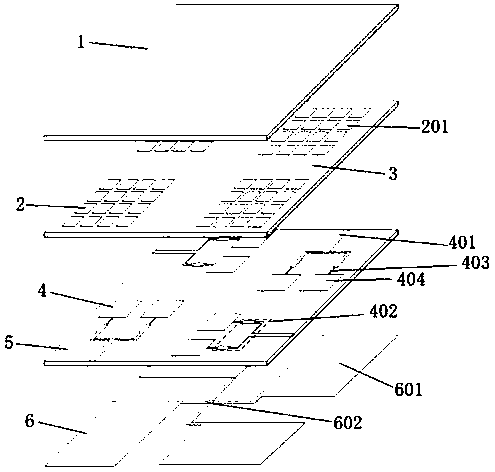
[0024] Such as figure 1 As shown, a metasurface-based multi-beam antenna includes an upper dielectric substrate 1, a metasurface layer 2, an intermediate dielectric substrate 3, a feed network layer 4, and a lower dielectric substrate 5 that are arranged coaxially from top to bottom. and a ground plate 6, an air layer is provided between the intermediate layer dielectric substrate 3 and the feed network layer 4, the metasurface layer 2 includes 4 metasurfaces 201, and each of the metasurfaces 201 consists of 4× 4 square metal patch arrays, the feed network layer 4 includes 4 feed units 401, and each feed unit 401 includes sequentially cascaded microstrip feeders 402, power splitters 403, impedance matching The microstrip line 404 and two No. 1 rectangular patches 405, and the four feed units 401 are arranged to rotate 90 degrees around the axis in turn. The ground plate 6 includes four No. 2 rectangular metal patches 601 and cross-shaped micro With a strip line 602, the four ...


PUM


Abstract

The invention belongs to the technical field of wireless communication, and particularly relates to a multi-beam antenna based on a metasurface. The invention aims to solve the technical problem thatan existing multi-beam antenna needs a complex beam forming network. The multi-beam antenna based on the metasurface comprises an upper dielectric substrate, a metasurface layer, a middle dielectric substrate, a feed network layer, a lower dielectric substrate and a grounding plate which are coaxially arranged in sequence from top to bottom, wherein an air layer is arranged between the middle dielectric substrate and the feed network layer; the beam width and gain of the antenna are improved by arranging the upper dielectric substrate; the electromagnetic field distribution above the feed network layer is improved by additionally arranging the metasurface layer on the middle dielectric substrate and arranging the feed network layer below the middle dielectric substrate, so that the beams are enabled to be inclined in a pitch angle plane. The antenna does not need to design a complex beam forming network, the metasurface and the dielectric substrate are used for realizing multiple beams, the structure is simple, and the beams can be changed in an azimuth plane.

Description

technical field [0001] The invention belongs to the technical field of wireless communication, and in particular relates to a metasurface-based multi-beam antenna. Background technique [0002] Multibeam antennas have promising applications in various fields such as satellite communications, radar systems, and wireless local area networks. At present, multi-beam antennas are usually implemented using a beamforming network to feed the antenna, such as a 4×4 Butler matrix, which consists of four 90° couplers, two cross couplers and two 45° phase shifters, which have four input and output ports, by stimulating one port at a time, a response with equal amplitude but different phases can be formed at the output port, thus forming four beams with different directions; (G.Tian, ​​J.-P.Yang, and W.Wu , "Butler Matrix Based Multi-Beam BaseStation Antenna Array," IEEE Trans.Antennas Propag., 67(2019), 5372–5379); Rotman lens-fed multi-beam antennas are designed using quasi-optical me...

Claims


Application Information

Patent Timeline
Patent Type & Authority Applications(China)
IPC IPC(8): H01Q1/48H01Q1/50H01Q1/52H01Q15/00
CPCH01Q1/48H01Q1/50H01Q1/52H01Q15/0086
Inventor 张文梅张佳楠苏晋荣陈新伟杨荣草
Owner SHANXI UNIV
Why Eureka
Eureka Blog
Learn More