
Machining method for manufacturing motor rotor punching sheet

A technology for rotor punching and motor rotors, which is used in the manufacture of stator/rotor bodies, manufacturing tools, metal processing equipment, etc., can solve the problems of unpolished, high defective product rate, excessive grinding, etc. The product has a high defective rate and the effect of preventing excessive grinding

Active Publication Date: 2020-05-08
福州中研电机有限公司
View PDF10 Cites 2 Cited by
  • Summary
  • Abstract
  • Description
  • Claims
  • Application Information

AI Technical Summary

Problems solved by technology

[0003] However, the following problems exist in the existing rotor punching and grinding. a. At present, a grinder is often used for rotor punching and grinding. The production quality of the punching sheet is a waste of cost; b, when the traditional rotor punching is polished, only a single rotor punching can be polished, the grinding efficiency is low, the product defective rate is high, and the grinding status of the rotor punching is inconsistent, which is easy to Leading to the scrapping of rotor punching, it can improve the yield of rotor punching and the grinding efficiency of rotor punching

Method used


Image

  • Machining method for manufacturing motor rotor punching sheet
  • Machining method for manufacturing motor rotor punching sheet
  • Machining method for manufacturing motor rotor punching sheet

Examples


Embodiment Construction

[0033] The embodiments of the present invention will be described in detail below with reference to the accompanying drawings, but the present invention can be implemented in many different ways defined and covered by the claims.

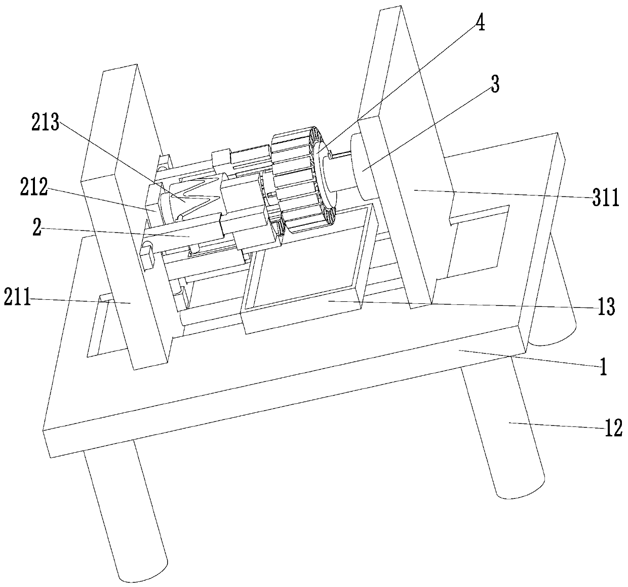
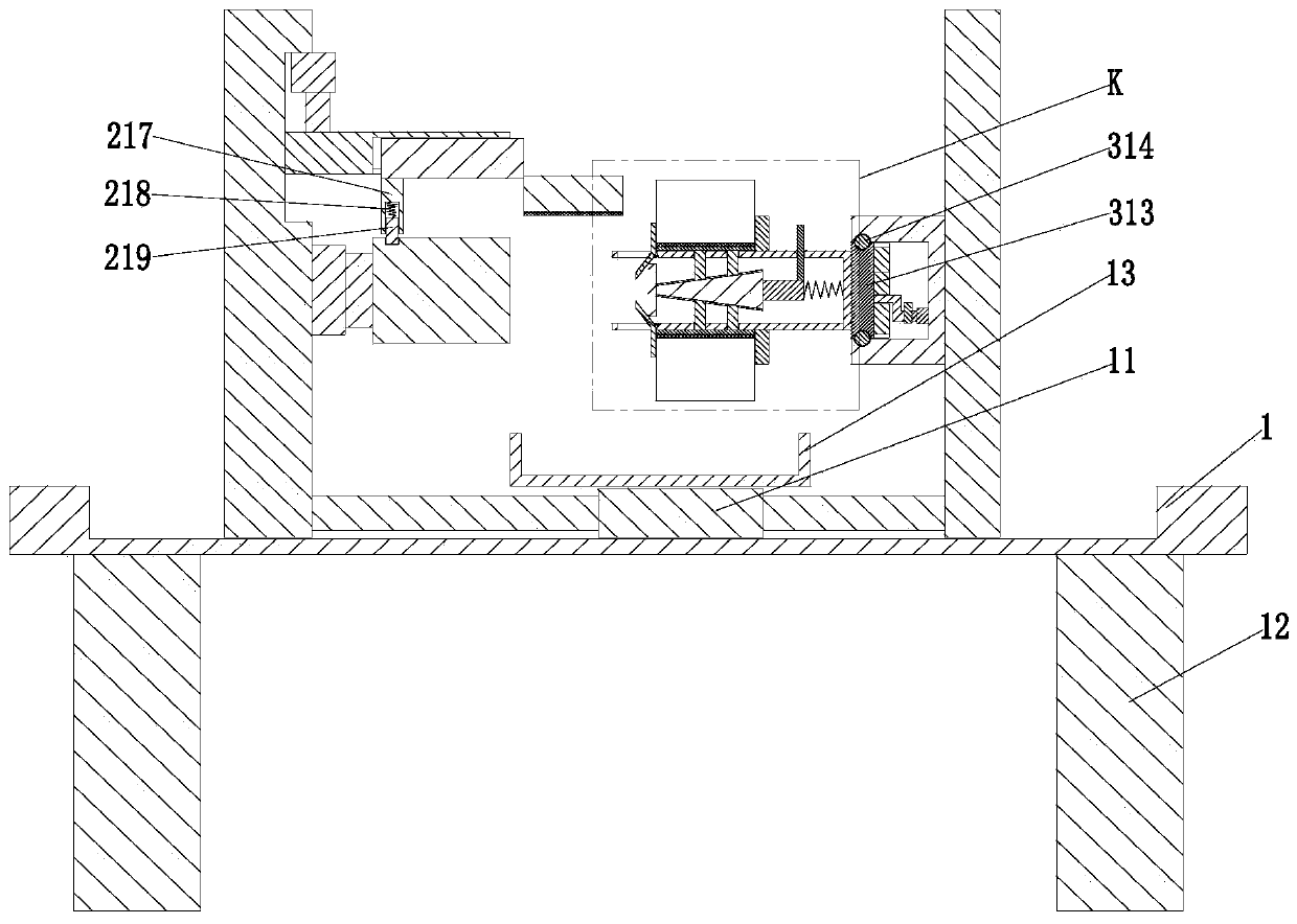
[0034] Such as Figure 1 to Figure 8 As shown, a machining method for making motor rotor punching is characterized in that it mainly includes the following manufacturing steps:

[0035] Step 1, punching the light sheet, punching the fixed rotor light sheet on a piece of sheet material manually using a stamping die to obtain the stator and rotor light sheet;

[0036]Step 2, separation of stamping, placing the stator and rotor light sheet obtained in step 1 into the mold, and separating the stator punch and rotor punch in the stator and rotor light sheet based on the positioning process hole to obtain the rotor punch;

[0037] Step 3, stamping operation, placing the rotor punch in step 2 into the stamping die, stamping the rotor punch, and obtaining ...


PUM


Abstract

The invention relates to a machining method for manufacturing a motor rotor punching sheet. The method mainly comprises the following steps of polished section punching, punched sheet separation, punching operation, polishing operation, detection processing, statistical counting and the like. Used rotor punching sheet grinding equipment comprises a bottom plate, a grinding device, a rotary positioning device and a clamping device. The machining method can be used to solve the following problems existing in grinding of an existing rotor punching sheet: a, a grinding machine is commonly used forgrinding the rotor punching sheet at present, a phenomenon that a slotted hole is not ground or excessive grinding occurs easily when the grinding machine grinds, and production quality of the rotorpunching sheet is reduced, and cost is wasted; and b, only a single rotor punching sheet can be ground when the traditional rotor punching sheet is ground, grinding efficiency is low, a defective rateof products is high, polishing conditions of the rotor punching sheets are inconsistent, and the rotor punching sheets are extremely easy to scrap. A yield of the rotor punching sheets and the grinding efficiency of the rotor punching sheets can be improved.

Description

technical field [0001] The invention relates to the technical field of motor processing, in particular to a machining method for making a punched sheet of a motor rotor. Background technique [0002] At present, motors are widely used in transportation, construction, industry and other fields. The motor is mainly composed of a stator and a rotor. The motor rotor is an indispensable and important part of the motor. The motor rotor is mainly composed of multiple rotor punches. There is a rotating shaft hole in the middle of the rotor punching sheet. After stacking, the rotating shaft holes on the rotor punching sheet are connected to each other, and then the rotating shaft is installed in the rotating shaft hole for use. The motor rotor will have a lot of burrs after stamping. It is necessary to clean the burrs on the motor rotor. Grinding treatment. [0003] However, the following problems exist in the existing rotor punching and grinding. a. At present, a grinder is often u...

Claims


Application Information

Patent Timeline
Patent Type & Authority Applications(China)
IPC IPC(8): H02K15/02B24B19/02B24B27/00B24B41/06B24B47/16
CPCB24B19/02B24B27/0069B24B27/0076B24B41/06B24B47/16H02K15/02
Inventor 高峰王彦洲
Owner 福州中研电机有限公司
Learn More