
Composite drainage tube fixing frame

A drainage tube and composite technology, applied in catheters, suction devices, medical science, etc., can solve problems such as medical safety and medical efficiency, and achieve the effects of preventing doctor-patient disputes, preventing complications, and promoting patient recovery.

Pending Publication Date: 2020-05-12
山西白求恩医院
View PDF8 Cites 0 Cited by
  • Summary
  • Abstract
  • Description
  • Claims
  • Application Information

AI Technical Summary

Problems solved by technology

[0003] In view of this, the object of the present invention is to provide a composite drainage tube holder to solve the medical safety and medical efficiency problems caused by the drainage tube in the clinical nursing process

Method used


Image

  • Composite drainage tube fixing frame
  • Composite drainage tube fixing frame
  • Composite drainage tube fixing frame

Examples


Embodiment 1

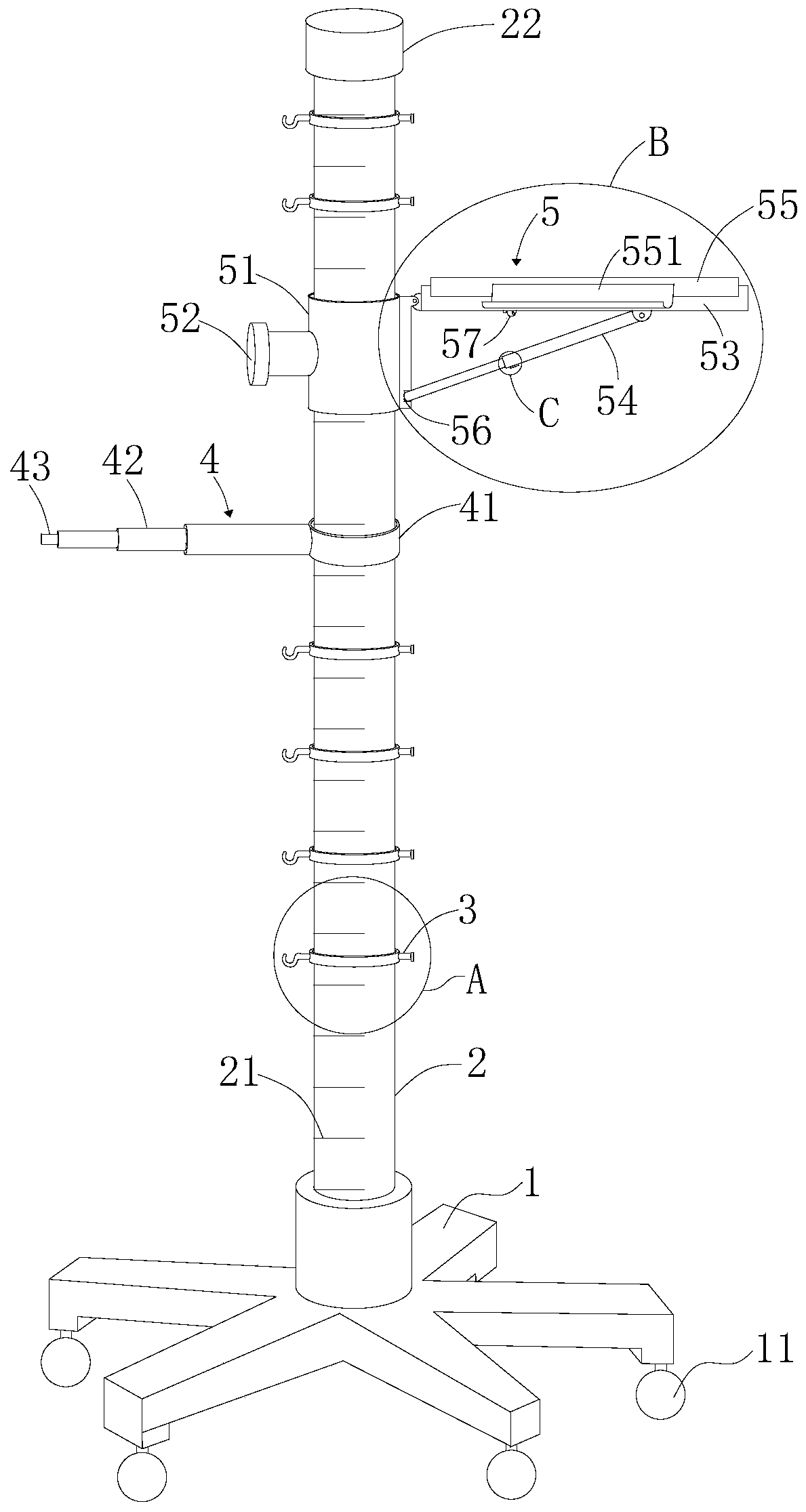
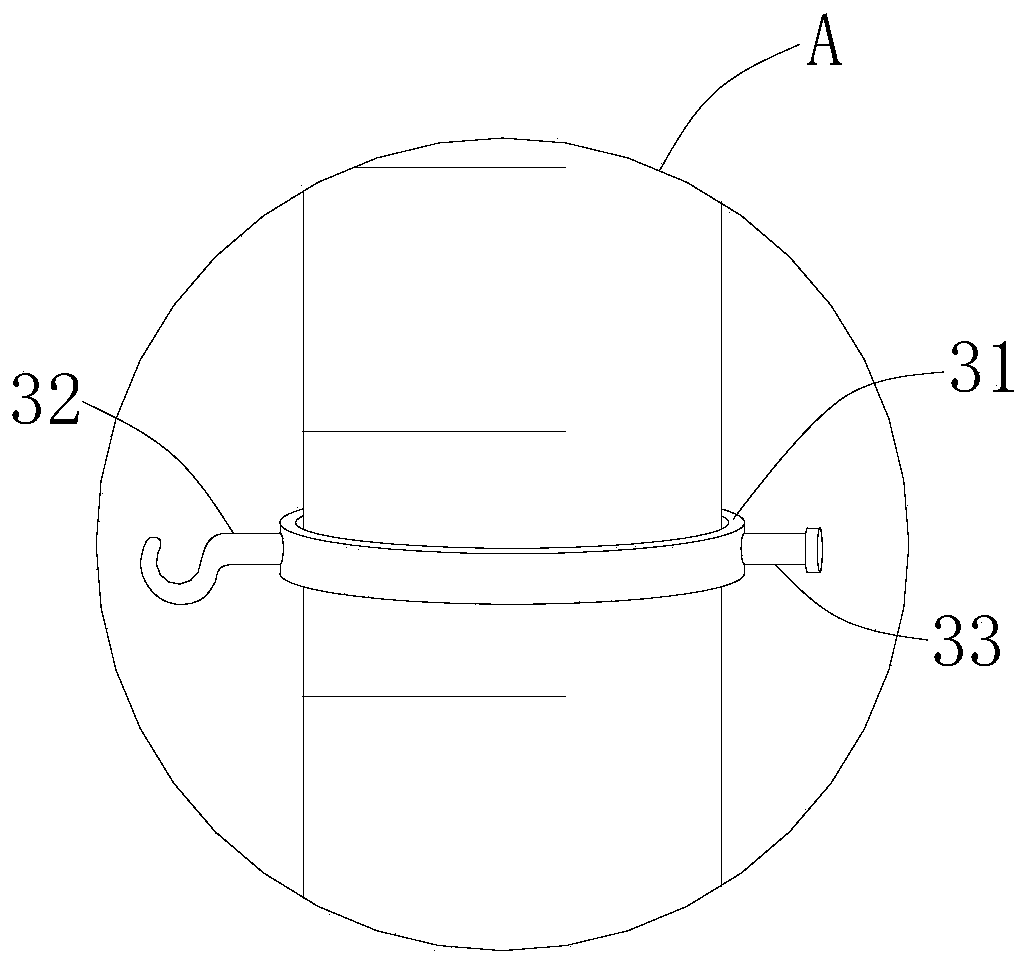
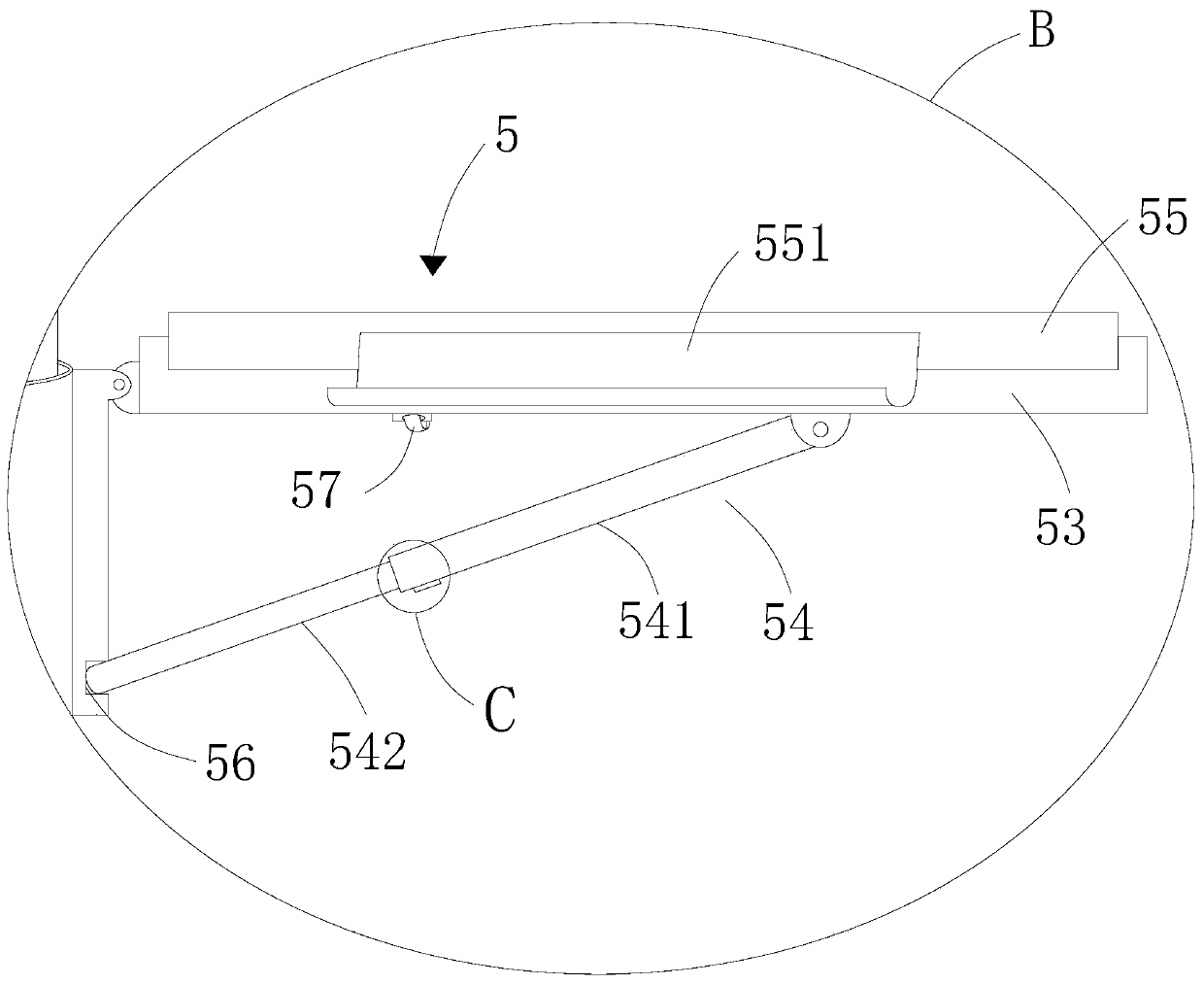
[0027] Such as Figure 1-6 As shown, the composite drainage tube fixing frame includes a movable base 1, and a support rod 2 is fixedly connected to the movable base 1. The length of the support rod 2 is 150 cm, and the diameter is 18 mm, which is used to accurately fix the suspension height of the drainage tube. The supporting rod 2 is provided with several annular structures 3, laser measuring devices 4 and tray fixing devices 5, the supporting rod 2 is provided with a standard scale 21, the minimum scale 21 is 1mm, and the scale 21 of the supporting rod 2 starts from the bottom. The 0mm at the end starts to end at 1500mm at the top, and there is a scale 21 continuing at the connection of the pallet fixing device 5, such as image 3 As shown, the annular structure 3 includes a fixed ring 31 sleeved on the support rod 2, a hook 32 is fixed on one end side wall of the fixed ring 31, and the bottom of the hook 32 and the lower edge of the fixed ring 31 flush, the other end sid...

Embodiment 2

[0030] Based on the structure of Embodiment 1, in Embodiment 2, the movable base 1 is screwed to the support rod 2 .

Embodiment 3

[0032] Based on the structure of embodiment 1, in embodiment 3, the movable base 1 is composed of five legs comprising universal wheels 11, and the bottom of the five legs of the movable base 1 is provided with universal wheels 11, and the movable base 1 moves through the universal wheel 11 set below it, except that the material of the universal wheel 11 is rubber, and the material of the movable base 1 is aluminum alloy, and the single leg is irregular, with a length of 200mm. The angle is 10°, which is used to support and fix the entire composite drainage tube fixing frame.

[0033] The universal wheel 11 is provided with a braking device, and the universal wheel 11 is fixed by the braking device.


PUM


Abstract

The invention discloses a composite drainage tube fixing frame which comprises a movable base, a supporting rod is fixed to the movable base, and a plurality of annular structures, a laser measuring device and a tray fixing device are arranged on the supporting rod. Nursing workers use the laser measuring device to measure the accurate height of the outlet of the drainage tube according to medicaladvice, adjust the height of the annular structure and then fix the annular structure, then the drainage bag is hung on the hook, and meanwhile the illness state change of a patient is observed through a cranial pressure monitor on the tray. By means of the composite drainage tube fixing frame, a plurality of drainage tubes and other pipelines can be managed at the same time, accurate fixing of the height of the drainage tubes can be achieved in clinical application of the drainage tubes, management efficiency of nursing staff is improved, rehabilitation of patients is promoted, and disputesbetween doctors and patients are prevented.

Description

technical field [0001] The invention belongs to the field of medical auxiliary equipment, and in particular relates to a composite drainage tube fixing frame. Background technique [0002] In clinical practice, neurosurgery patients need to stay in bed for a long time to recover after craniocerebral surgery. During this period, different types, different heights, and different numbers of drainage tubes should be properly fixed according to the type of disease and the patient's condition. At the same time, changes in the patient's intracranial pressure should be monitored in real time through the intracranial pressure monitor. At present, strings, gauze bandages, adhesive plasters and other materials are commonly used in clinical practice to fix the drainage tube on the bedside frame. The fixed height of the drainage tube is basically adjusted by visual inspection. This is not only very inaccurate, the process is very cumbersome, and it is safe. It is also relatively low; an...

Claims


Application Information

Patent Timeline
Patent Type & Authority Applications(China)
IPC IPC(8): A61M25/02A61M1/00A61B50/33A61B5/03
CPCA61M1/0023A61B5/031A61M25/02A61M2025/028A61B50/33
Inventor 吴志萍王晶晶
Owner 山西白求恩医院
Learn More