Bearing side network system, mobile-fixed coexistence fusion system and deployment method thereof
A network system and network technology, applied in the field of mobile-solid coexistence fusion system and its deployment, and the field of bearer side network systems, can solve the problems of too many mobile communication service bearer layers, long network delay time, traffic detour, etc.
- Summary
- Abstract
- Description
- Claims
- Application Information
AI Technical Summary
Problems solved by technology
Method used
Image
Examples
no. 1 example
[0033] Embodiments of the present invention propose a mobile-fixed coexistence fusion system, which can realize fixed-mobile fusion.
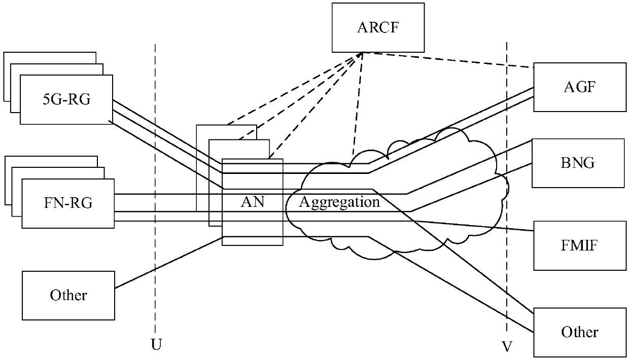
[0034] figure 2 It is a schematic structural diagram of a mobile-fixed coexistence fusion system according to an embodiment of the present invention, as shown in figure 2 As shown, the mobile-fixed coexistence fusion system may include: a bearer-side network system, an access-side network system, a core-side network system, and the Internet; the bearer-side network system is respectively connected to the access-side network system, the core-side network system, and the Internet.
[0035] Here, the network system on the access side is used to implement mobile communication access and fixed communication access; in practical applications, the evolved base station (eNodeB, eNB) can be used to implement mobile communication access.
[0036] The bearer-side network system includes: a mobile-fixed bearer IP metropolitan area network for realizing...
no. 2 example
[0064] In order to better reflect the purpose of the present invention, further illustrations are made on the basis of the first embodiment of the present invention.
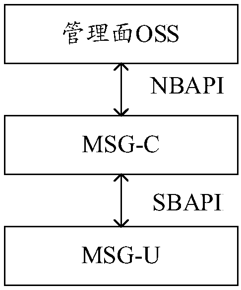
[0065] According to the content described in the foregoing embodiments, by Figure 4 A schematic diagram of the network architecture of the mobile-fixed coexistence fusion system according to the embodiment of the present invention is given, Figure 4 In the figure, the dotted line represents the control message, and the implementation represents the forwarding message; MSG-C and S / PGW-C are in the control cloud, and MSG-U is in the forwarding cloud. When a mobile communication service user (such as a mobile phone user) initiates a network access request In this case, communication with S / PGW-U can be realized based on integrated service optical transport network (UTN) convergence, mobile network data service (referred to as mobile network data service), and UTN access; fixed communication services can include b...
no. 3 example
[0094] In order to better reflect the purpose of the present invention, further illustrations are made on the basis of the foregoing embodiments of the present invention.
[0095] For the mobile-fixed coexistence fusion system of the foregoing embodiments of the present invention, the following typical examples can be used to illustrate the unified bearer implementation of different services on the mobile-fixed coexistence fusion system.
PUM
 Abstract
Description
Claims
Application Information
 - R&D
- Intellectual Property
- Life Sciences
- Materials
- Tech Scout
- Unparalleled Data Quality
- Higher Quality Content
- 60% Fewer Hallucinations
Browse by: Latest US Patents, China's latest patents, Technical Efficacy Thesaurus, Application Domain, Technology Topic, Popular Technical Reports.
© 2025 PatSnap. All rights reserved.Legal|Privacy policy|Modern Slavery Act Transparency Statement|Sitemap|About US| Contact US: help@patsnap.com


