
Forced cyclone sand removal device structure

A device structure and swirl de-sanding technology, applied in swirling devices, devices whose axial directions of swirling flow can be reversed, etc. The effect of preventing leakage

Inactive Publication Date: 2020-05-15
GUANGDONG POWER GRID CO LTD +1
View PDF1 Cites 4 Cited by
  • Summary
  • Abstract
  • Description
  • Claims
  • Application Information

AI Technical Summary

Problems solved by technology

[0007] (1) After the existing cyclone forced desanding device works for a period of time, the bottom outlet is blocked by the separated solid particles, which also affects the separation efficiency of the cyclone, and there is no effective solution. squeeze damage
[0008] (2) The drilling fluid at the overflow port of the existing hydrocyclone forced desanding device may be mixed with some small particles of sand and gravel, and gravity is difficult to separate it from the viscous drilling fluid, resulting in drilling fluid containing fine sand. Damage equipment when transmitting hydraulic power or cooling and lubricating drill bits and drill strings, and the purity of drilling fluid will be affected and the effect of other work will be reduced
[0009] (3) The flush nozzle installed on the inner wall of the improved version of the existing hydrocyclone forced desanding device is used to flush the small grit that is difficult to remove attached to the inner wall, which accumulates for a long time, causing the inner wall of the cyclone to wear when it rotates, and The existing spray pipes are difficult to ensure strong spraying ability and cannot guarantee to remove the attached sand particles. Secondly, the water flow of the water pipe is very large, which causes a lot of waste of water resources, which does not conform to my country's resource-saving development strategy.

Method used


Image

  • Forced cyclone sand removal device structure
  • Forced cyclone sand removal device structure
  • Forced cyclone sand removal device structure

Examples


Embodiment Construction

[0041] In order to make the purpose, features and advantages of the present invention more obvious and understandable, the technical solutions in the embodiments of the present invention will be clearly and completely described below in conjunction with the accompanying drawings in the embodiments of the present invention. Obviously, the following The described embodiments are only some, not all, embodiments of the present invention. Based on the embodiments of the present invention, all other embodiments obtained by persons of ordinary skill in the art without making creative efforts belong to the protection scope of the present invention.

[0042] In the description of the present invention, it should be understood that the orientations or positional relationships indicated by the terms "upper", "lower", "top", "bottom", "inner" and "outer" are based on those shown in the accompanying drawings. Orientation or positional relationship is only for the convenience of describing ...


PUM


Abstract

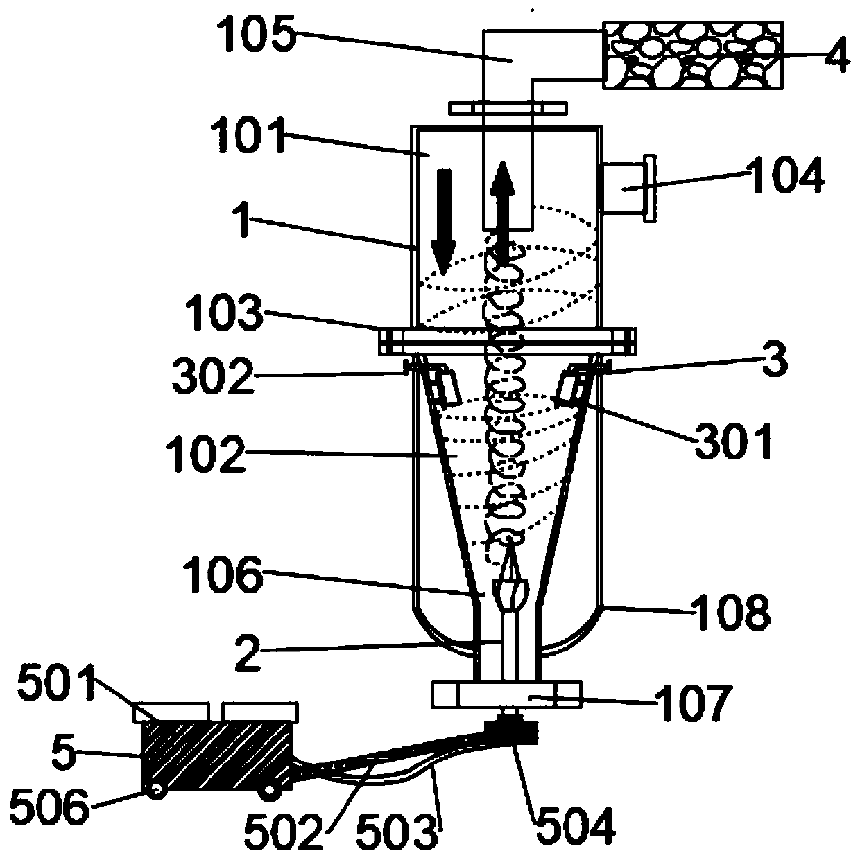
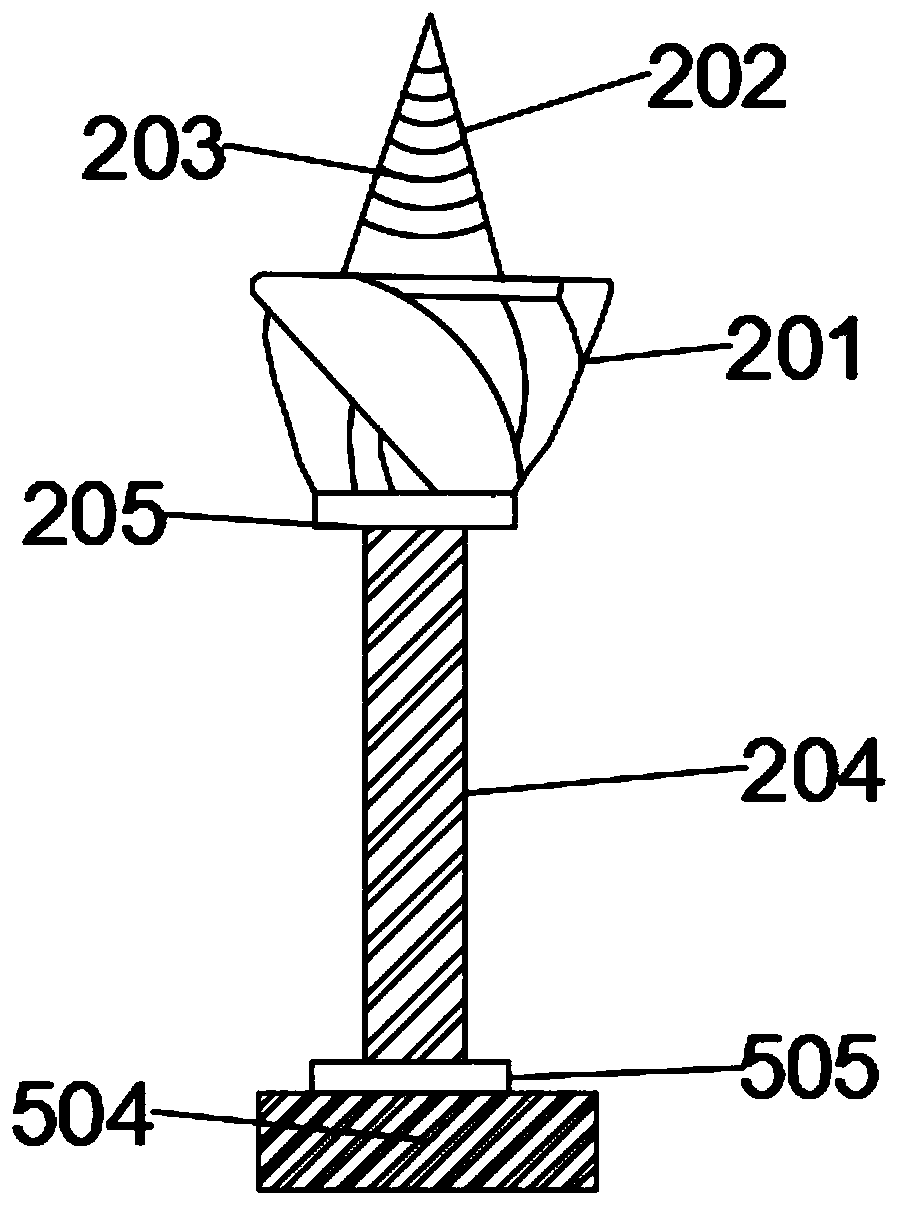
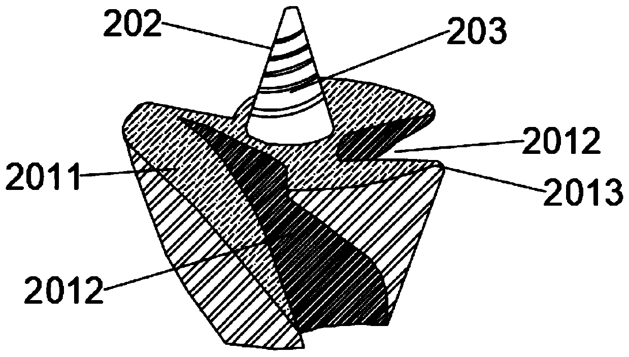
The invention discloses a forced cyclone sand removal device structure. The forced cyclone sand removal device structure comprises an inverted cone cyclone body, wherein the inverted cone cyclone bodycomprises an upper cyclone barrel body; the lower end of the upper cyclone barrel body is connected with a lower cone angle cyclone barrel body; a mixed phase liquid inlet is formed in the upper right end of the upper cyclone barrel body; a liquid phase outlet is formed in the just upper end of the upper cyclone barrel body; a sand outlet is formed in the bottom end of the lower cone angle cyclone barrel body; a sand dredger is arranged at the sand outlet; a throttling sand removal atomizing nozzle is arranged at the upper end of the inner wall of the lower cone angle cyclone barrel body; theright side of the liquid phase outlet is connected with a liquid phase sand removal protector; and the left side of the sand dredger is connected with a rotating power device. According to the forcedcyclone sand removal device structure, the sand dredger is designed to effectively prevent sand from being blocked, the arranged liquid phase sand removal protector can effectively and thoroughly remove fine sand in a liquid phase, and the arranged throttling sand removal atomizing nozzle can save a large amount of water resources by utilizing the atomizing design while removing the sand in the inverted cone cyclone body.

Description

technical field [0001] The invention relates to the technical field of swirl sand removal, in particular to a forced swirl sand removal device structure. Background technique [0002] The cyclone is a separation device for different phase mixtures, which separates the two-phase or multi-phase fluid with a certain density difference through the centrifugal force generated by the strong rotation inside it. When the separation medium in the cyclone is water or other liquid, it is called hydrocyclone, and when the separation medium is air, it is called wind cyclone or cyclone separator. The structure, separation process and principle of the two are basically the same. Because the cyclone has the advantages of simple structure, convenient operation, large production capacity, high separation efficiency, small footprint, no transmission parts and easy automatic control, it has been widely used in many fields of the national economy. Hydrocyclones are widely used in major oil fiel...

Claims


Application Information

Patent Timeline
Patent Type & Authority Applications(China)
IPC IPC(8): B04C5/08B04C5/181B04C5/22B04C9/00
CPCB04C5/08B04C5/181B04C5/22B04C9/00
Inventor 陈炽锋
Owner GUANGDONG POWER GRID CO LTD
Learn More