Flow-following semi-solid forming method and device
A semi-solid forming and following technology, applied in the field of semi-solid processing of metal materials and semi-solid squeeze casting, can solve the problems of high cost and low production efficiency, and achieve the effect of cost reduction, high preparation efficiency and excellent comprehensive performance.
- Summary
- Abstract
- Description
- Claims
- Application Information
AI Technical Summary
Problems solved by technology
Method used
Image
Examples
Embodiment 1
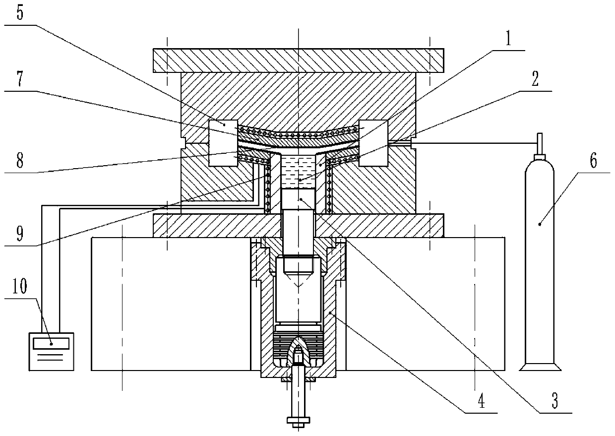
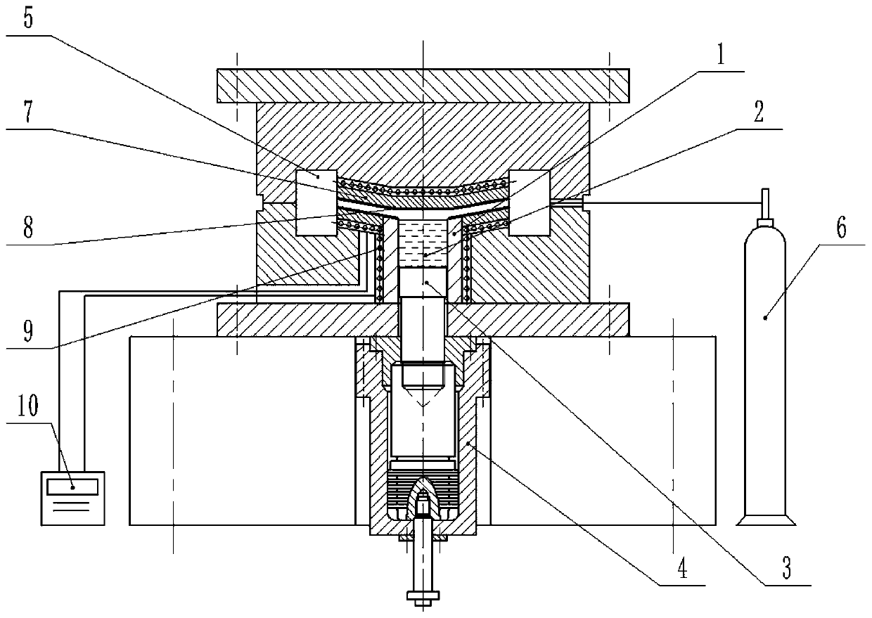
[0044] A flowing semi-solid forming device, comprising: a barrel 1, a pressure head 3, a flow channel 7 and a temperature control system 10;
[0045] The barrel 1 is a barrel-shaped cavity, and one end of the barrel 1 is connected with the mould,
[0046]The pressure head 3 is a cylinder, the diameter of the pressure head 3 is 0.2-1.0 mm smaller than the inner diameter of the barrel 1, and the length is 85 mm. One end of the pressure head 3 is connected with the piston rod of the pressurizing cylinder 4 through a connecting rod, and the pressure The other end of the head 3 extends into the barrel 1 and can move freely in the barrel 1,
[0047] One end of the flow channel 7 communicates with the barrel 1, and forms an included angle of 22° with the axis of the barrel 1, and the other end of the flow channel 7 communicates with the mold cavity 5,
[0048] The temperature control system 10 includes: a heating element 9 and its temperature control instrument. The temperature cont...
Embodiment 2
[0058] A flowing semi-solid forming device, comprising: a barrel 1, a pressure head 3, a flow channel 7 and a temperature control system 10;
[0059] The barrel 1 is a barrel-shaped cavity, and one end of the barrel 1 is connected with the mould,
[0060] The pressure head 3 is a cylinder, the diameter of the pressure head 3 is 0.2-1.0 mm smaller than the inner diameter of the barrel 1, and the length is 85 mm. One end of the pressure head 3 is connected with the piston rod of the pressurizing cylinder 4 through a connecting rod, and the pressure The other end of the head 3 extends into the barrel 1 and can move freely in the barrel 1,
[0061] One end of the flow channel 7 communicates with the barrel 1, and forms an included angle of 22° with the axis of the barrel 1, and the other end of the flow channel 7 communicates with the mold cavity 5,
[0062] The temperature control system 10 includes: a heating element 9 and its temperature control instrument. The temperature con...
Embodiment 3
[0072] A flowing semi-solid forming device, comprising: a barrel 1, a pressure head 3, a flow channel 7 and a temperature control system 10;
[0073] The barrel 1 is a barrel-shaped cavity, and one end of the barrel 1 is connected with the mould,
[0074] The pressure head 3 is a cylinder, the diameter of the pressure head 3 is 0.2-1.0 mm smaller than the inner diameter of the barrel 1, and the length is 85 mm. One end of the pressure head 3 is connected with the piston rod of the pressurizing cylinder 4 through a connecting rod, and the pressure The other end of the head 3 extends into the barrel 1 and can move freely in the barrel 1,
[0075] One end of the flow channel 7 communicates with the barrel 1, and forms an included angle of 22° with the axis of the barrel 1, and the other end of the flow channel 7 communicates with the mold cavity 5,
[0076] The temperature control system 10 includes: a heating element 9 and its temperature control instrument. The temperature con...
PUM
| Property | Measurement | Unit |
|---|---|---|
| Granularity | aaaaa | aaaaa |
Abstract
Description
Claims
Application Information
 - R&D
- Intellectual Property
- Life Sciences
- Materials
- Tech Scout
- Unparalleled Data Quality
- Higher Quality Content
- 60% Fewer Hallucinations
Browse by: Latest US Patents, China's latest patents, Technical Efficacy Thesaurus, Application Domain, Technology Topic, Popular Technical Reports.
© 2025 PatSnap. All rights reserved.Legal|Privacy policy|Modern Slavery Act Transparency Statement|Sitemap|About US| Contact US: help@patsnap.com


