Punching head and manufacturing method thereof and composite small grinding head

A manufacturing method and punching head technology, which are applied to grinding devices, manufacturing tools, grinding machine parts, etc., can solve the problems of difficult to guarantee precision, low brazing strength, poor practicability, etc. The effect of improving connection strength and service life

Pending Publication Date: 2020-05-15
宋京新 +1
View PDF0 Cites 0 Cited by
  • Summary
  • Abstract
  • Description
  • Claims
  • Application Information

AI Technical Summary

Problems solved by technology

Cylindrical indenters are difficult to process! In addition, because the cylindrical indenter is thin and the accuracy is difficult to guarantee, the gap between the molds will cause insufficient compactness of the sintered body, which directly affects the strength of the sintered body itself.
[0005] Because the welding surface of sintering brazing is extremely small and the brazing strength is low, it is difficult to ensure the strength required for the punching head when it is used, and it is very easy to break the diamond layer and the matrix. The production process is complicated and the practicability is poor.

Method used


Image

  • Punching head and manufacturing method thereof and composite small grinding head
  • Punching head and manufacturing method thereof and composite small grinding head
  • Punching head and manufacturing method thereof and composite small grinding head

Examples


Embodiment 1

[0057] like Figure 1 to Figure 7 As shown, a method for making a punching head includes the following steps:

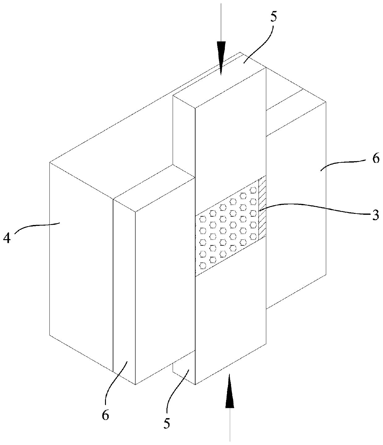
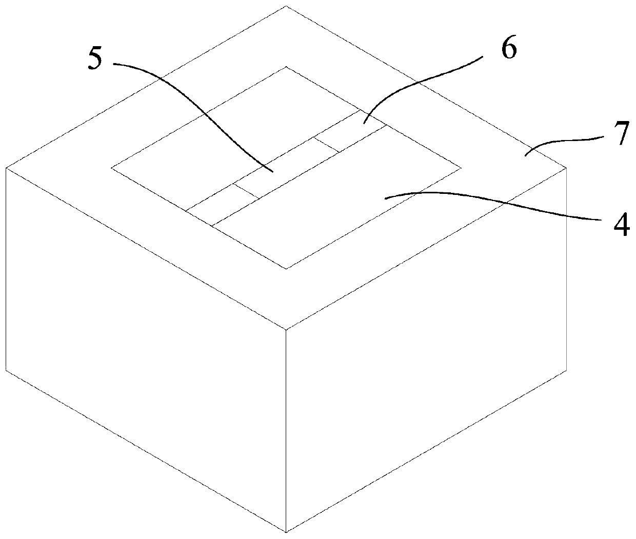
[0058] Step 1. Arrange the two first outer molds 4 in parallel, and put the sintered body powder mixture 3 between the two first outer molds 4; arrange the two second outer molds 6 between the two first outer molds 4 , the two second outer molds 6 are respectively located at both ends of the sintered powder mixture 3; the mold frame 7 is then fitted around the two first outer molds 4;

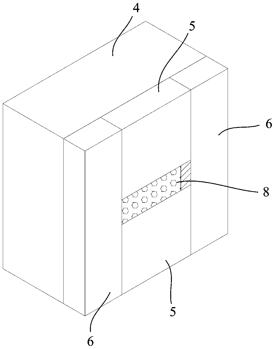
[0059] Step 2. Two sheet-shaped indenters 5 are located between the two first outer molds 4, and are respectively located at the upper and lower ends of the sintered body powder mixture 3; The mixture 3 is compressed, and the sintered body powder mixture 3 is laterally compressed, and the sintered body powder mixture 3 is compressed into a powder metallurgy sintered body 8 with a cuboid structure;

[0060] Step 3. The upper end of the cuboid-structured powder metallurgy sintered bod...

Embodiment 2

[0071] like figure 1 , figure 2 , image 3 , Figure 8 , Figure 9 and Figure 10 As shown, a method for making a punching head includes the following steps:

[0072] Step 1. Arrange the two first outer molds 4 in parallel, and put the sintered body powder mixture 3 between the two first outer molds 4; arrange the two second outer molds 6 between the two first outer molds 4 , the two second outer molds 6 are respectively located at both ends of the sintered powder mixture 3; the mold frame 7 is then fitted around the two first outer molds 4;

[0073] Step 2. Two sheet-shaped indenters 5 are located between the two first outer molds 4, and are respectively located at the upper and lower ends of the sintered body powder mixture 3; The mixture 3 is compressed, and the sintered body powder mixture 3 is laterally compressed, and the sintered body powder mixture 3 is compressed into a powder metallurgy sintered body 8 with a cuboid structure;

[0074] Step 3. The upper end o...

Embodiment 3

[0085] A punching head, the punching head 2 is made of impregnated multi-layer diamond.

[0086] The punching head made of the sintered body is an impregnated multi-layer diamond with a self-sharpening grinding layer; the service life is greatly improved, so that the other grinding sections of the composite small grinding head can be fully utilized.


PUM


Abstract

The invention relates to a punching head and a manufacturing method thereof and a composite small grinding head. The manufacturing method comprises the following steps that a sintering body powder mixture is compressed through a mold and two flaky pressing heads, lateral pressing is carried out on the sintering body powder mixture; and the sintering body powder mixture is pressed into a powder metallurgy sintering body of a cuboid structure; and the upper end of the powder metallurgy sintering body is machined to be of a cylindrical structure, the lower end of the powder metallurgy sintering body is machined to be of a hemispheric structure, and the punching head is obtained. According to the punching head, the pressing strength can be greatly improved, the portion causing the insufficientdensity of the sintering body due to pressure losses caused by a mold clearance can be located at a corner and is finally cut off, and the quality of the punching head is ensued; and by means of a laser welding manner, the punching head and a grinding head base are solidified, the punching head achieving high-strength connection can be obtained, and the composite small grinding head is manufactured.

Description

technical field [0001] The invention relates to the technical field of grinding, in particular, to a punching head and a manufacturing method thereof, and a composite small grinding head. Background technique [0002] In the prior art, at present, electroplating grinding heads, or small grinding heads combining electroplating and sintering are used for punching and edging of glass screens of mobile phones. For the processing of round holes with a diameter of about Φ1mm and smaller (or strip holes with the same diameter and width), an electroplated diamond small grinding head is usually used for grinding and drilling, and then a forming grinding section with a smaller diameter is used to grind the holes that have been drilled. The hole edge of the good hole is chamfered and edged. On the same grinding head, one or more granularity and multi-functional grinding sections are generally set. Among the above-mentioned small grinding heads, the punching head is generally set as a...

Claims


Application Information

Patent Timeline
Patent Type & Authority Applications(China)
IPC IPC(8): B24B41/04B24D18/00B22F3/02B22F3/03B22F7/06
CPCB22F3/02B22F3/03B22F7/06B24B41/04B24D18/0009B24D18/009
Inventor 宋京新龙慧玲梁安宁赵亮王志勇刘人杰
Owner 宋京新
Why Eureka
Try Eureka