Heat dissipation device for tower drum of wind turbine generator

A technology for heat sinks and wind turbines, applied in wind power generation, wind turbines, cooling/ventilation/heating transformation, etc., can solve the problems of short airflow stroke, reduced heat dissipation efficiency, low cooling efficiency, etc., to extend the stroke and avoid over-temperature , The effect of improving heat dissipation efficiency

Inactive Publication Date: 2020-05-15
CSIC CHONGQING HAIZHUANG WINDPOWER EQUIP
View PDF7 Cites 1 Cited by
  • Summary
  • Abstract
  • Description
  • Claims
  • Application Information

AI Technical Summary

Problems solved by technology

However, since there is no seal between the tower platform and the tower wall, part of the airflow will be directly discharged from the air outlet after entering the tower, so that part of the cold air cannot participate in heat exchange, resulting in relatively low cooling efficiency, and it is impossible to avoid electrical components. In case of localized overheating
The airflow stroke of the above air-cooling structure is similar to a "C" shape, and the air inlet and outlet are located close to each other. Since the airflow flows in the direction of pressure drop, the closer to the air outlet, the greater the pressure drop, so the airflow is larger, and part of the airflow has no time to participate. The heat dissipation has already been discharged, resulting in a reduction in heat dissipation efficiency, and it is easy to cause local overheating of electrical components, and the airflow stroke is also short, which cannot settle the sand and dust

Method used


Image

  • Heat dissipation device for tower drum of wind turbine generator
  • Heat dissipation device for tower drum of wind turbine generator
  • Heat dissipation device for tower drum of wind turbine generator

Examples


Embodiment Construction

[0023] The following will clearly and completely describe the technical solutions in the embodiments of the present invention with reference to the accompanying drawings in the embodiments of the present invention. Obviously, the described embodiments are only some, not all, embodiments of the present invention. Based on the embodiments of the present invention, all other embodiments obtained by persons of ordinary skill in the art without making creative efforts belong to the protection scope of the present invention.

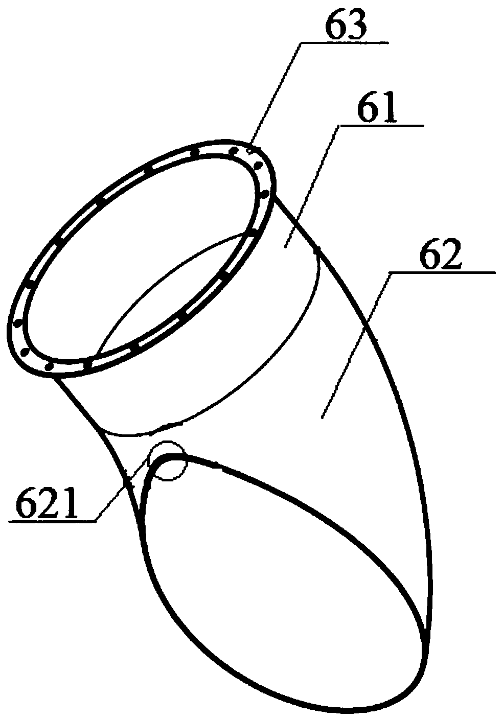
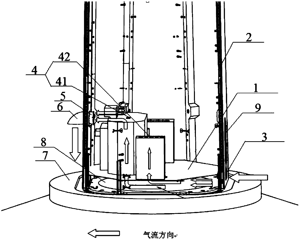
[0024] See figure 1 , which shows a schematic structural view of a wind turbine tower cooling device provided by an embodiment of the present invention, which may include: a tower platform 1 located at the bottom of the tower and sealed with the tower wall 2, a tower platform 1 arranged on the tower The tower air inlet 3 below the platform 1 and located on the tower wall 2, the exhaust fan 5 installed on the tower wall 2 opposite the tower air inlet 3 and loca...


PUM


Abstract

The invention discloses a heat dissipation device for a tower drum of a wind turbine generator. The heat dissipation device comprises a tower drum platform which is positioned at the bottom of the tower drum and is sealed with the wall of the tower drum; a tower drum air inlet formed below the tower drum platform and located in the tower drum wall, an exhaust fan installed on the tower drum wall opposite to the tower drum air inlet and located at the position of an air outlet of an electrical component in the tower drum, and an air duct which is connected with the exhaust fan and is located atthe outer side of the tower drum wall, and also comprises a grating plate which is arranged at a preset position of the tower drum platform and is used for introducing air entering from the tower drum air inlet into the electrical component, wherein the preset position is a position corresponding to the air inlet of the electrical component. According to the technical scheme disclosed by the invention, the cold air entering the tower drum can be fully utilized to dissipate the heat of the corresponding electrical components, so that the tower drum or the electrical components in the tower drum are prevented from being overheated, and the noise reduction and the sand and dust sedimentation can also be realized.

Description

technical field [0001] The invention relates to the technical field of wind turbines, and more specifically, to a cooling device for a tower of a wind turbine. Background technique [0002] Wind turbines are equipped with heat-generating electrical components such as tower base control cabinets, converters, and transformers inside the tower. The heat generated by these electrical components during operation slowly accumulates inside the tower, causing the temperature of the tower to rise. The rise in temperature may lead to failure of electrical components or even safety accidents, so it is necessary to dissipate heat from the tower and the electrical components inside the tower. [0003] At present, the heat dissipation methods of electrical components inside the tower are divided into water cooling and air cooling. The principle of water cooling is that the hot air inside the electrical components exchanges heat with the cooling liquid, and then the cooling liquid transfer...

Claims


Application Information

Patent Timeline
Patent Type & Authority Applications(China)
IPC IPC(8): H05K7/20F03D80/80
CPCF03D80/82H05K7/20136Y02E10/72
Inventor 龚波涛黄金余陈帅张洪溢贺国凌
Owner CSIC CHONGQING HAIZHUANG WINDPOWER EQUIP
Why Eureka
Try Eureka