
A combined hanging device for a double-deck ring header

An annular header and hanging device technology, applied in the chemical industry, can solve the problems of unsatisfactory support effect, uncompact structure, and many consumables, etc., and achieve the effect of reasonable and reliable force, safe structure, and reduction of overall gravity load.

Active Publication Date: 2021-07-20
HARBIN BOILER
View PDF0 Cites 0 Cited by
  • Summary
  • Abstract
  • Description
  • Claims
  • Application Information

AI Technical Summary

Problems solved by technology

[0004] In order to solve the problem that the existing simple cantilever beam structure has unsatisfactory support effect, many consumable materials and uncompact structure, it further provides a combined hanging device for double-layer annular header

Method used


Image

  • A combined hanging device for a double-deck ring header
  • A combined hanging device for a double-deck ring header
  • A combined hanging device for a double-deck ring header

Examples


specific Embodiment approach 1

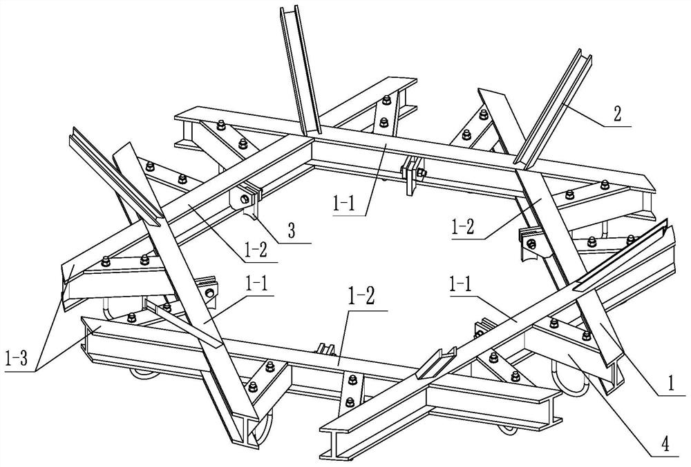
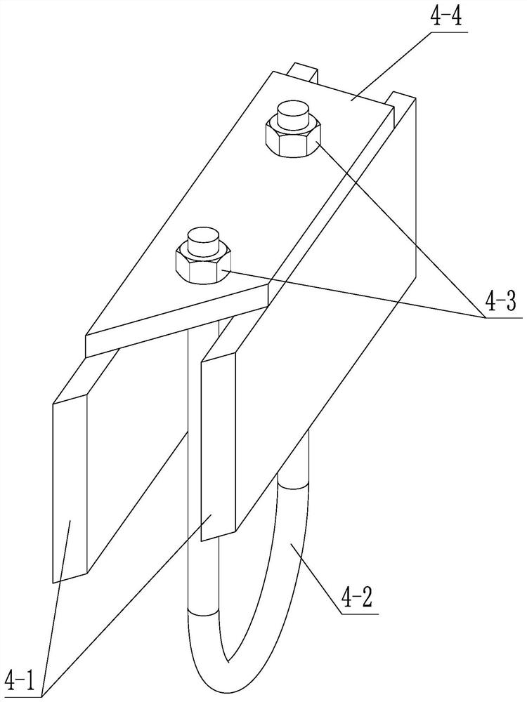
[0025] Specific implementation mode one: combine figure 1 and Figure 4 Describe this embodiment mode, a kind of combined suspension device for double-layer annular header of this embodiment mode, it comprises hexagonal star structure beam (1), six oblique tie bars (2), six cantilever lifting lugs of inner ring header component (3) and twelve outer ring header hanging beam components (4), the hexagonal star structure beam (1) includes three main beams (1-1), three middle short beams (1-2) and six Two end short beams (1-3), three main beams (1-1) are horizontally arranged on the same plane in a circular array, and an intermediate short beam is arranged between two adjacent main beams (1-1). Beams (1-2), the three intermediate short beams (1-2) are horizontally arranged on the same plane in a circular array, and the two adjacent main beams (1-1) are far away from the intermediate short beams (1- One side of 2) is respectively provided with an end short beam (1-3), and the two ...

specific Embodiment approach 2

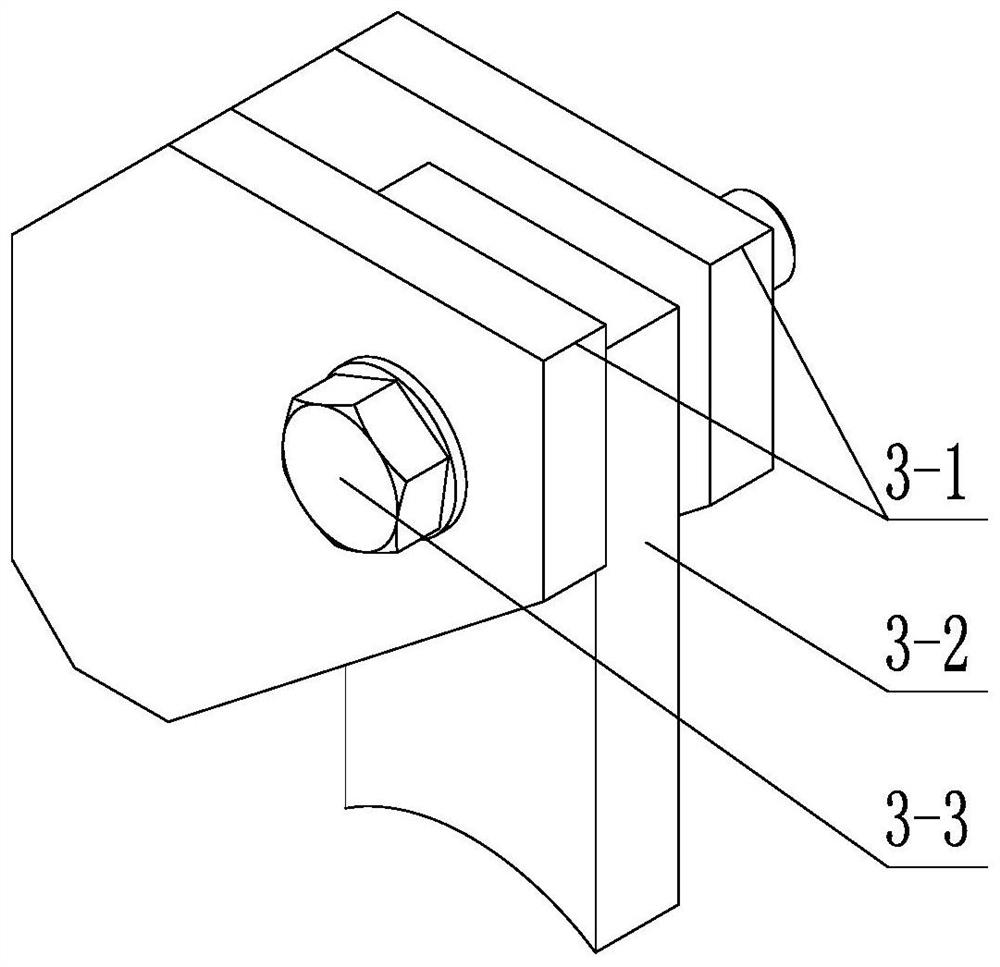
[0028] Specific implementation mode two: combination figure 1 and figure 2 To illustrate this embodiment, each inner ring header cantilever lug assembly 3 of this embodiment includes a hanging plate 3-2, a connecting element 3-3 and two lugs 3-1, and the two lugs 3-1 are vertically The vertical direction is arranged parallel to the inner end surface of the main beam 1-1 or the inner end surface of the intermediate short beam 1-2, the hanging plate 3-2 is located between the two ear plates 3-1, and the hanging plate 3-2 is connected by The element 3-3 is fixedly connected with the two ear plates 3-1, and the lower end surface of the hanging plate 3-2 is provided with an arc surface matching the outer cylindrical surface of the inner ring header 5. With such arrangement, the reliable bearing of the inner ring header 5 can be realized through the six inner ring header cantilever lug assemblies 3, and the number of the inner ring header cantilever eye assemblies 3 can also be fl...

specific Embodiment approach 3

[0032] Specific implementation mode three: combination figure 1 and figure 2To illustrate this embodiment, the straight lines formed between all the centrally symmetrical two suspension plates 3-2 among the six suspension plates 3-2 of this embodiment converge at one point, and this point coincides with the center of circle of the inner ring header 5. Other compositions and connections are the same as those in Embodiment 1 or Embodiment 2.


PUM


Abstract

The utility model relates to a combined hanging device for a double-layer annular header, which relates to the technical field of chemical industry. The invention solves the problems that the existing simple cantilever beam structure has unsatisfactory supporting effect, many consumable materials and uncompact structure. In the present invention, an intermediate short beam is arranged between two adjacent main beams, and an end short beam is respectively provided on the side of the adjacent two main beams far away from the intermediate short beam, and the six oblique ties are arranged in a circular array. The method is installed on the top of the six-pointed star structural beam with an outward slope, and the lower end of the diagonal tie is fixed on the upper end surface of the main beam at the intersection of the main beam and the intermediate short beam. The middle part of the inner end surface of each main beam and the inner end surface of each intermediate short beam There is an inner ring header cantilever lug assembly in the middle, and an outer lug assembly is provided between the two ends of each main girder and two adjacent intermediate short girders, and between each end short girder and adjacent main girders. Ring header suspension beam assembly. The invention is used to realize the reliable bearing of the inner ring header and the outer ring header.

Description

technical field [0001] The invention relates to the technical field of chemical industry, in particular to a combined hanging device for double-layer annular headers. Background technique [0002] With the continuous development of chemical technology and the strict requirements of the country on environmental protection and energy efficiency, the utilization of waste heat and waste heat in chemical processes has been continuously paid attention to; traditional refractory materials must be stopped and replaced regularly, which causes heat loss, poor energy efficiency indicators, and low economic benefits. ;In recent years, the water cooling wall has begun to be used in large-scale chemical pressure equipment such as gasifiers and waste heat boilers; due to the characteristics of pressure equipment, the shell adopts a circular shape, so the internal water cooling wall also needs to adopt a ring or polygonal structure; this brings Come to the hanging problem of the ring header...

Claims


Application Information

Patent Timeline
Patent Type & Authority Patents(China)
IPC IPC(8): B65D90/00
CPCB65D90/00
Inventor 刘彬超唐卉李明方小里沈洁李玉伟毕艳飞
Owner HARBIN BOILER
Learn More