
Self-snow-melting system for airport terminal viaduct

A technology for viaducts and terminal buildings, which is applied to bridges, bridge parts, bridge construction, etc. It can solve the problems of a large number of people and snow plows, large traffic volume, and the aging resistance of viaduct asphalt, so as to ensure the safe driving of vehicles, The effect of preventing traffic accidents and ensuring smooth traffic

Pending Publication Date: 2020-05-19
高志斌 +1
View PDF0 Cites 0 Cited by
  • Summary
  • Abstract
  • Description
  • Claims
  • Application Information

AI Technical Summary

Problems solved by technology

[0002] Most of the airport terminal viaducts are the only passage to the departure floor of the terminal. They have the characteristics of large slopes, large bending ranges, and large traffic volumes. In winter, the viaducts of airport terminal buildings are icing and snow-covered, which reduces the friction coefficient of the bridge surface and The longer the braking distance, the more prone to traffic accidents
At present, the airport terminal viaduct mainly uses mechanical deicing and snow-melting agents to melt snow and ice, but the snow-melting agent has many negative effects on the asphalt surface of the viaduct and the surrounding environment. Decreased stability, damage to the surrounding soil ecological environment, and pollution of water sources; the use of mechanical deicing methods requires a large number of personnel and snowplows, and the deicing effect is not complete and lags seriously

Method used


Image

  • Self-snow-melting system for airport terminal viaduct
  • Self-snow-melting system for airport terminal viaduct
  • Self-snow-melting system for airport terminal viaduct

Examples


Embodiment Construction

[0026] The principles and features of the present invention will be described below in conjunction with the accompanying drawings, and the examples given are only used to explain the present invention, and are not used to limit the scope of the present invention.

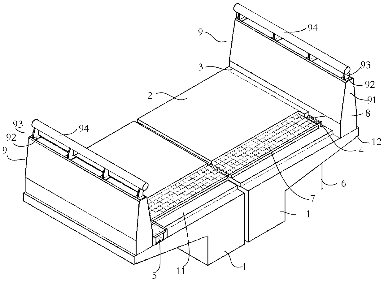
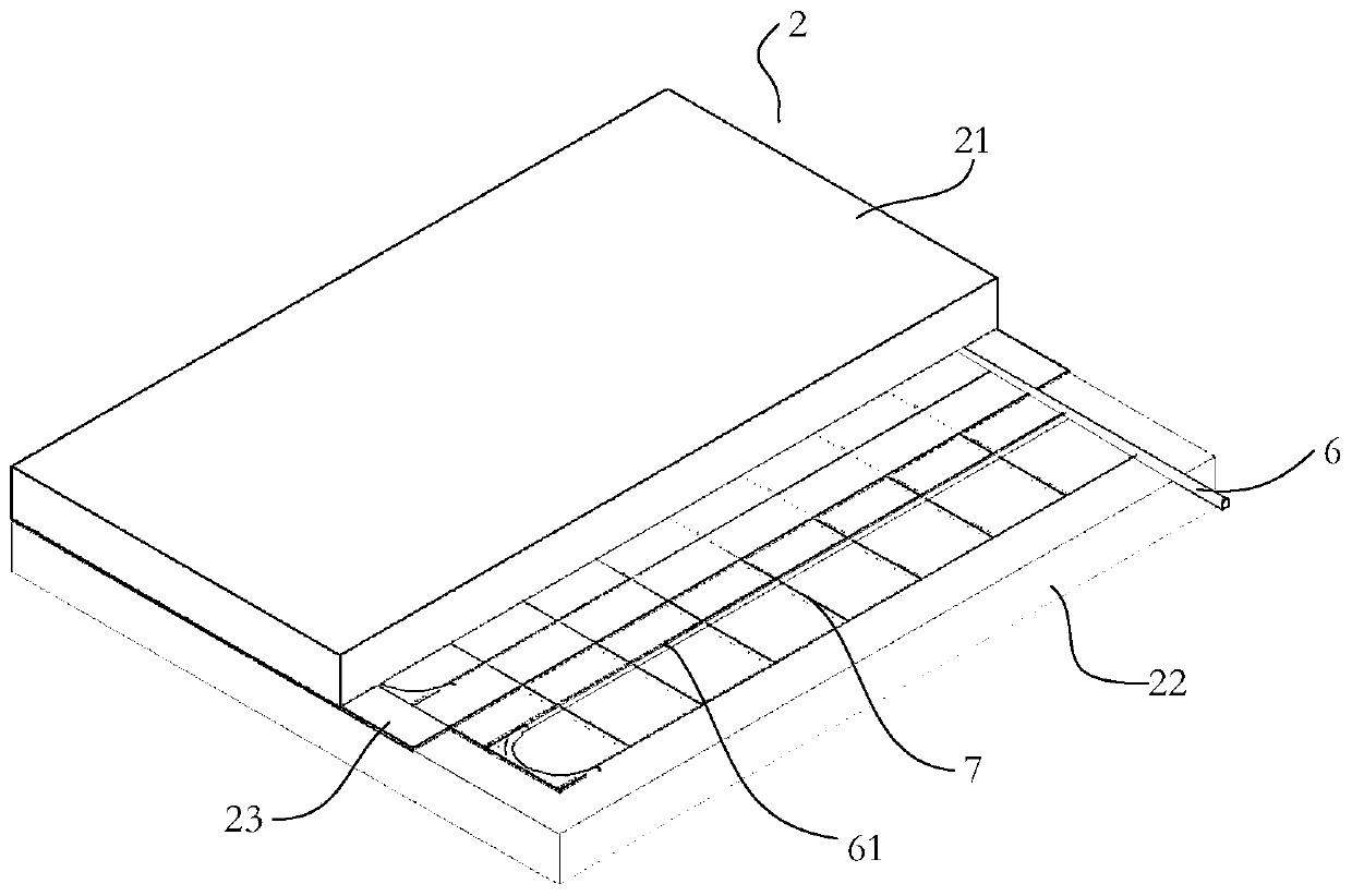
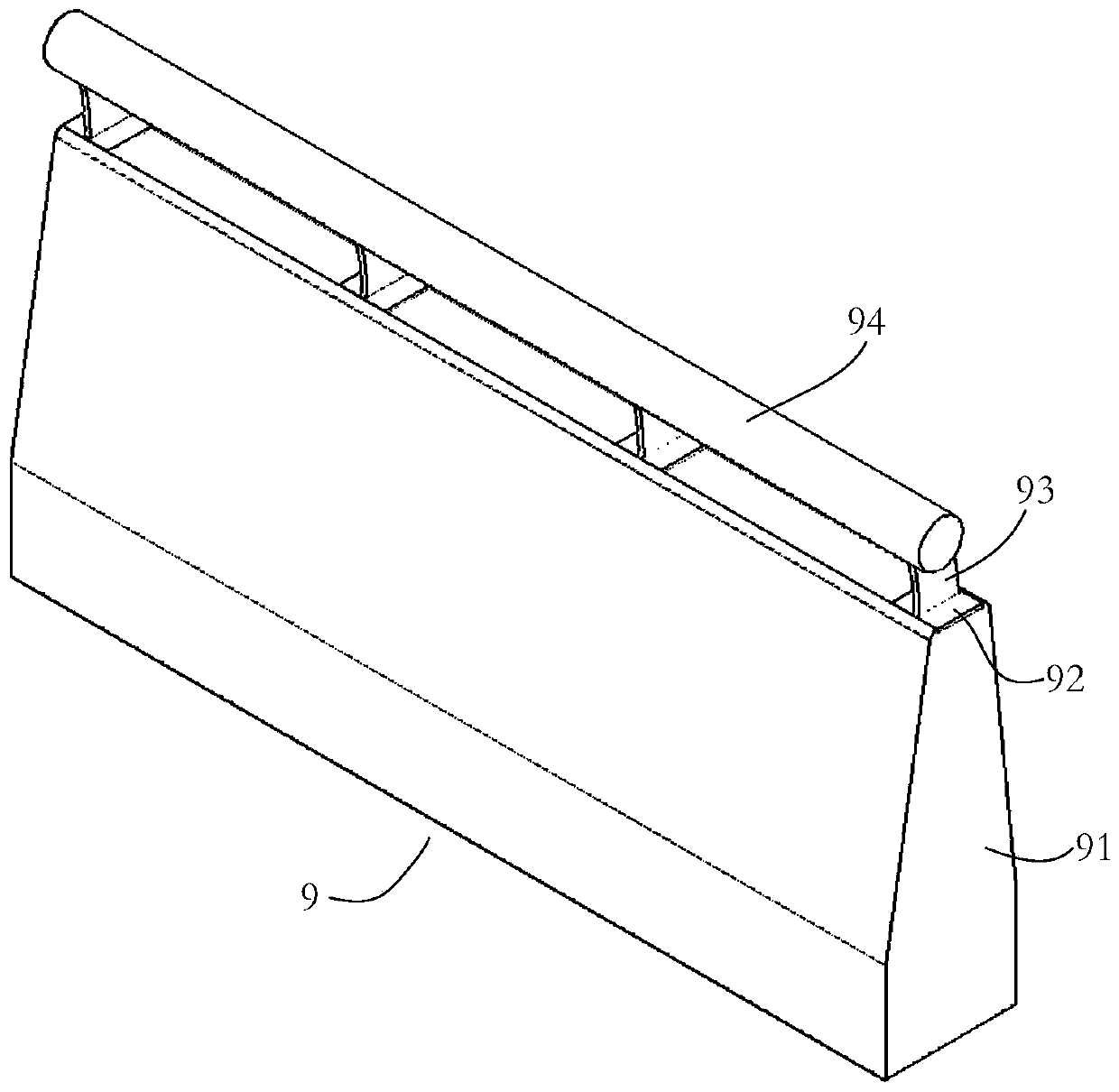
[0027] Such as Figure 1-Figure 4 As shown, a self-melting snow system for an airport terminal viaduct in this embodiment is installed in the box girder 1 of the viaduct; it includes a heating line 61, and the heating line 61 is laid in the asphalt snow melting layer 2 on the box girder 1. The box girder 1 is provided with a cable trough 3, a downline hole 4 and a drainage ditch 5, and the cable 6 connected to the heating wire 61 is laid in the cable trough 3 and connected to the box girder 1 through the downline hole 4. Power supply; the drainage ditch 5 communicates with the upper surface of the asphalt snowmelt layer 2 .

[0028] In this embodiment, heating wires are laid in the asphalt snow-melting layer on the...


PUM


Abstract

The invention relates to a self-snow-melting system for an airport terminal viaduct. The self-snow-melting system is installed in the box girder of the viaduct. The system comprises a heating wire, the heating wire is laid in an asphalt snow melting layer on a box girder, a cable groove, a cable discharging hole and a drainage ditch are formed in the box girder, and a cable connected with the heating wire is laid in the cable groove and led out of the box girder through the cable discharging hole to be connected with a power source. The drainage ditch is communicated with the upper surface ofthe asphalt snow melting layer. According to the invention, the heating wires are laid in the asphalt snow melting layer on the viaduct box girder, electric energy is converted into heat energy to heat the asphalt bridge deck, the functional requirement for real-time snow melting and deicing of the viaduct is met, ice and snow on the viaduct deck of the airport terminal building can be quickly andautomatically melted in winter, traffic accidents are prevented, and smooth traffic of the viaduct and safe driving of vehicles are guaranteed.

Description

technical field [0001] The invention relates to a viaduct self-melting snow system, in particular to an airport terminal viaduct self-melting snow system. Background technique [0002] Most of the airport terminal viaducts are the only passage to the departure floor of the terminal. They have the characteristics of large slopes, large bending ranges, and large traffic volumes. In winter, the viaducts of airport terminal buildings are icing and snow-covered, which reduces the friction coefficient of the bridge surface and The braking distance becomes longer and traffic accidents are prone to occur. At present, the airport terminal viaduct mainly uses mechanical deicing and snow-melting agents to melt snow and ice, but the snow-melting agent has many negative effects on the asphalt surface of the viaduct and the surrounding environment. Decreased stability, destruction of the surrounding soil ecological environment, and water pollution; the use of mechanical deicing methods r...

Claims


Application Information

Patent Timeline
Patent Type & Authority Applications(China)
IPC IPC(8): E01D19/08E01C11/26E01D19/10E01D2/04
CPCE01C11/26E01C11/265E01D2/04E01D19/086E01D19/103
Inventor 高志斌刘岩来勇王跃孙士博
Owner 高志斌
Learn More