Bus encoding sending circuit and method, bus transmission system

A bus coding and transmitting circuit technology, applied in the field of microelectronics, can solve the problems of occupation, reducing coupling capacitance, increasing redundant signal lines, etc.

Active Publication Date: 2021-08-03
LOONGSON TECH CORP
View PDF0 Cites 0 Cited by
  • Summary
  • Abstract
  • Description
  • Claims
  • Application Information

AI Technical Summary

Problems solved by technology

Among them, increasing the spacing between adjacent signal lines can reduce the coupling capacitance, which in turn can reduce crosstalk. Specifically, the spacing between each signal line can be forcibly specified in the wiring, but it will take up too many routing resources, which is not suitable for wiring resources. Limited integrated circuits; space coding is to arrange a shielding line in parallel on both sides of each signal line to block the crosstalk intrusion of other signal lines, but there will still be coupling capacitance between the signal line and the shielding line; bus coding is usually based on The worst vector theory, adding an encoder at the sending end, the worst vector that the encoder will appear in the process of transmitting the bus signal (that is, the situation where the signal bits transmitted by adjacent signal lines are reversed at the same time), through The bus encoding method is treated as a non-worst vector, but the bus encoding method eliminates bus crosstalk and still increases redundant signal lines, thereby occupying too many routing resources

Method used


Image

  • Bus encoding sending circuit and method, bus transmission system
  • Bus encoding sending circuit and method, bus transmission system
  • Bus encoding sending circuit and method, bus transmission system

Examples


Embodiment Construction

[0056] In order to make the purpose, technical solutions and advantages of the embodiments of the present invention clearer, the technical solutions in the embodiments of the present invention will be clearly and completely described below in conjunction with the drawings in the embodiments of the present invention. Obviously, the described embodiments It is a part of the embodiments of the present invention, but not all of them. Based on the embodiments in the embodiments of the present invention, all other embodiments obtained by persons of ordinary skill in the art without making creative efforts belong to the protection scope of the embodiments of the present invention.

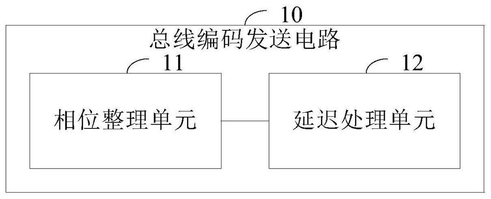
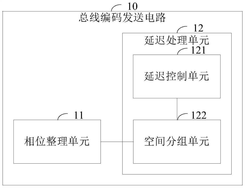
[0057] figure 1 The structural representation of the bus coding transmission circuit provided by the present invention, as figure 1 As shown, the bus coding sending circuit 10 of this embodiment includes: a phase sorting unit 11 and a delay processing unit 12 connected in sequence.

[0058] Wherein, the...


PUM


Abstract

The invention provides a bus coding sending circuit and method, and a bus transmission system. The circuit includes: a phase sorting unit and a delay processing unit connected in sequence; wherein, the phase sorting unit is used to sort the initial phases of each signal bit in the initial bus signal into the same initial phase; and send the sorted initial phase to the delay processing unit The bus signal; the delay processing unit is used to group each signal bit in the sorted bus signal; and each group of signal bits in the grouped bus signal according to the corresponding delay time The duration is set to be different, and the delay duration corresponding to the first signal bit in each signal bit group is set to the same preset delay mode for delay; and the delayed bus signal is sent to the bus decoding receiving circuit. The present invention avoids the occurrence of the worst crosstalk situation and reduces the transmission delay caused by the crosstalk under the premise that the wiring resource requirement remains unchanged.

Description

technical field [0001] The invention relates to the technical field of microelectronics, in particular to a bus encoding sending circuit and method, and a bus transmission system. Background technique [0002] In integrated circuit design, when transmitting a multi-bit data signal, such as 16-bit data or 32-bit data signal, etc., the bus mode is often used for transmission. Since the bus is a collection of signal lines, and one signal line transmits one bit of data, a signal that can transmit multiple bits of data through a set of signal lines is usually called a bus signal. [0003] Different from the signal transmission method of one bit data, the arrangement of each signal line for the transmission bus signal is relatively dense and neat, and the length of each signal line is the same, and the surrounding electromagnetic environment is similar, which is beneficial to the bus signal after it is sent from the sending end. Reach multiple receivers at the same time, with con...

Claims


Application Information

Patent Timeline
Patent Type & Authority Patents(China)
IPC IPC(8): G06F13/16H04L12/40
CPCG06F13/161H04L12/40
Inventor 王江嵋崔明艳
Owner LOONGSON TECH CORP
Why Eureka
Try Eureka