Backboard of optical display module and preparation method thereof

A technology of optical display and display panel, which is applied to housings with display/control units, electrical equipment housings/cabinets/drawers, instruments, etc. It can solve problems such as low production efficiency, large pollution, and single functionality of the backplane. Achieve high production efficiency, low production cost, and no environmental pollution

Pending Publication Date: 2020-05-19
SUZHOU ENBRIGHTECH
View PDF0 Cites 0 Cited by
  • Summary
  • Abstract
  • Description
  • Claims
  • Application Information

AI Technical Summary

Problems solved by technology

However, the use of this process to produce the backplane will cause great pollution to the environment and low production efficiency. Moreo

Method used


Image

  • Backboard of optical display module and preparation method thereof
  • Backboard of optical display module and preparation method thereof
  • Backboard of optical display module and preparation method thereof

Examples


Embodiment 1

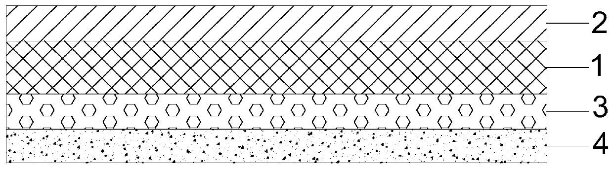
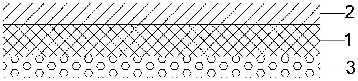
[0030] Such as figure 1 As shown, the backplane provided by this embodiment 1 includes a light reflective coating 2, a substrate 1 and a conductive anti-oxidation coating 3 arranged in sequence from top to bottom; the light reflective coating 2 is arranged on the substrate 1 near the light guide plate On one side, the conductive anti-oxidation coating 3 is arranged on the side of the substrate 1 away from the light guide plate;

[0031] Among them, the light reflective coating is a coating formed by adding titanium dioxide and additives with epoxy resin as the base material. Specifically, in this embodiment 1, the raw materials for the preparation of the light reflective coating include the following components in parts by mass: 35 parts of epoxy resin, 25 parts of water, 5 parts of dispersant, 5 parts of thickener, 10 parts of titanium dioxide share. After mixing and stirring the above-mentioned raw materials evenly, a light-reflective coating slurry is prepared; then, the ...

Embodiment 2

[0034] Such as figure 1 As shown, the backplane provided by this embodiment 2 includes a light reflective coating 2, a substrate 1 and a conductive anti-oxidation coating 3 arranged in sequence from top to bottom; the light reflective coating 2 is arranged on the substrate 1 near the light guide plate On one side, the conductive anti-oxidation coating 3 is arranged on the side of the substrate 1 away from the light guide plate;

[0035] Among them, the light reflective coating is a coating formed by adding titanium dioxide and additives with epoxy resin as the base material. Specifically, in this embodiment 2, the preparation raw material of light reflective coating comprises the following components of mass fraction: 55 parts of epoxy resins, 35 parts of water, 8 parts of dispersants, 6 parts of thickeners, 35 parts of titanium dioxide share. After mixing and stirring the above-mentioned raw materials evenly, a light-reflective coating slurry is prepared; then, the light-re...

Embodiment 3

[0038] Such as figure 1 As shown, the backplane provided in Example 3 includes a light reflective coating 2, a substrate 1, and a conductive anti-oxidation coating 3 arranged in sequence from top to bottom; the light reflective coating 2 is arranged on the substrate 1 near the light guide plate On one side, the conductive anti-oxidation coating 3 is arranged on the side of the substrate 1 away from the light guide plate;

[0039] Among them, the light reflective coating is a coating formed by adding titanium dioxide and additives with epoxy resin as the base material. Concretely, in this embodiment 3, the preparation raw material of light reflective coating comprises the following components of mass fraction: epoxy resin 75 parts, water 50 parts, dispersant 10 parts, thickener 10 parts, titanium dioxide 50 parts share. After mixing and stirring the above-mentioned raw materials evenly, a light-reflective coating slurry is prepared; then, the light-reflective coating slurry i...


PUM


Abstract

The invention discloses a backboard of an optical display module. The optical display module comprises a display panel, a light guide plate and the backboard. The backboard comprises a light reflection coating, a substrate and a conductive anti-oxidation coating which are sequentially arranged from top to bottom, wherein the light reflection coating is arranged on the side, close to the light guide plate, of the substrate, and the conductive anti-oxidation coating is arranged on the side, away from the light guide plate, of the substrate. The invention further provides a preparation method ofthe backboard of the optical display module. The backboard integrates a light reflection function, an anti-static function, a fixing function and an anti-oxidation function, and can meet high use requirements; a multifunctional slurry coating mode is adopted in the preparation process of the backboard, so that environmental pollution is avoided, the production efficiency is high, and the production cost is low.

Description

technical field [0001] The invention belongs to the technical field of optical display modules, in particular to a back plate of an optical display module and a preparation method thereof. Background technique [0002] A display backlight module generally includes components such as a display panel, a light guide plate, a reflector, and a backplane. The light guide plate converts the line light source into a surface light source, so that the light guide plate emits light evenly. The reflective sheet is arranged between the light guide plate and the back plate, and its function is to reflect the light exposed on the bottom surface of the light guide plate back into the light guide plate, so as to improve the use efficiency of light. The backplane is generally made of metal material, and functions to fix and protect the entire backlight module. [0003] In addition, in the prior art, the production process of electroplating or spraying is generally used for the backplane to ...

Claims


Application Information

Patent Timeline
IPC IPC(8): H05K5/00H05K5/02H05F3/00G09F9/30
CPCG09F9/30H05F3/00H05K5/0017H05K5/0213H05K5/0217
Inventor 王泽勇吴运阁
Owner SUZHOU ENBRIGHTECH
Why Eureka
Try Eureka