
Micro electrochemical machining electrode, machining method thereof, and micro electrochemical machining device

A kind of micro electrolysis and electrode technology, applied in the direction of processing electrodes, electric processing equipment, electrochemical processing equipment, etc., can solve the problem of inability to achieve efficient and stable processing of large-depth three-dimensional microstructures, meet the processing requirements, ensure the processing environment, The effect of promoting timely updates

Pending Publication Date: 2020-05-22
SHENZHEN UNIV
View PDF0 Cites 7 Cited by
  • Summary
  • Abstract
  • Description
  • Claims
  • Application Information

AI Technical Summary

Problems solved by technology

[0003] The purpose of the present invention is to provide a micro-electrolytic machining electrode and its processing method, and a micro-electrolytic machining device, aiming to solve the technical problem that the micro-electrolytic machining electrodes in the prior art cannot realize efficient and stable processing of large-depth three-dimensional microstructures

Method used


Image

  • Micro electrochemical machining electrode, machining method thereof, and micro electrochemical machining device
  • Micro electrochemical machining electrode, machining method thereof, and micro electrochemical machining device
  • Micro electrochemical machining electrode, machining method thereof, and micro electrochemical machining device

Examples


Embodiment Construction

[0037] Embodiments of the present invention are described in detail below, examples of which are shown in the drawings, wherein the same or similar reference numerals designate the same or similar elements or elements having the same or similar functions throughout. Attached below by reference Figure 2-6 The described embodiments are exemplary and are intended to explain the present invention, but should not be construed as limiting the present invention.

[0038]In describing the present invention, it should be understood that the terms "length", "width", "upper", "lower", "front", "rear", "left", "right", "vertical", The orientation or positional relationship indicated by "horizontal", "top", "bottom", "inner", "outer", etc. are based on the orientation or positional relationship shown in the drawings, and are only for the convenience of describing the present invention and simplifying the description, rather than Nothing indicating or implying that a referenced device or ...


PUM


Abstract

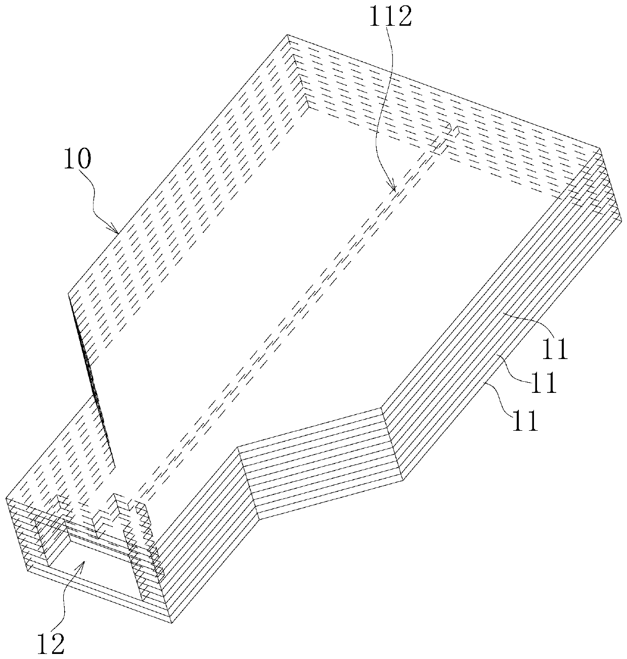
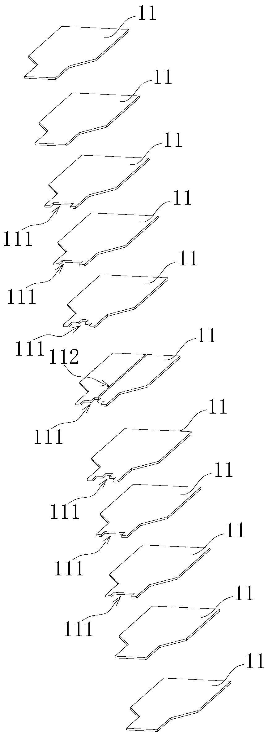
The invention belongs to the technical field of micro electrochemical machining, and particularly relates to a micro electrochemical machining electrode, a machining method thereof, and a micro electrochemical machining device. The micro electrochemical machining electrode comprises a plurality of electrode sheets, the electrode sheets are sequentially arranged in a laminated mode to form an electrode sheet assembly, two-dimensional microstructures used for machining a workpiece are arranged at one ends of a plurality of electrode sheets in the electrode sheet assembly, and the two-dimensionalmicrostructures are arranged in one-to-one correspondence and define a three-dimensional chamber which is adaptive to the shape of a three-dimensional microstructure on the workpiece; and circulationgrooves are formed in the surfaces of one or more electrode sheets in the electrode sheet assembly, the first ends of the circulation grooves extend out of the corresponding electrode sheets, and thesecond ends of the circulation grooves communicate with the three-dimensional chamber. According to the micro electrochemical machining electrode, the timely renewal of an electrolyte and the rapid discharge of electrolytic products in a machining area are accelerated, a good machining environment is ensured, the situation that a ''dead water area'' appears when the surface of a complex microstructure is machined is avoided, and the machining and using requirements of the large-depth three-dimensional microstructure can be met.

Description

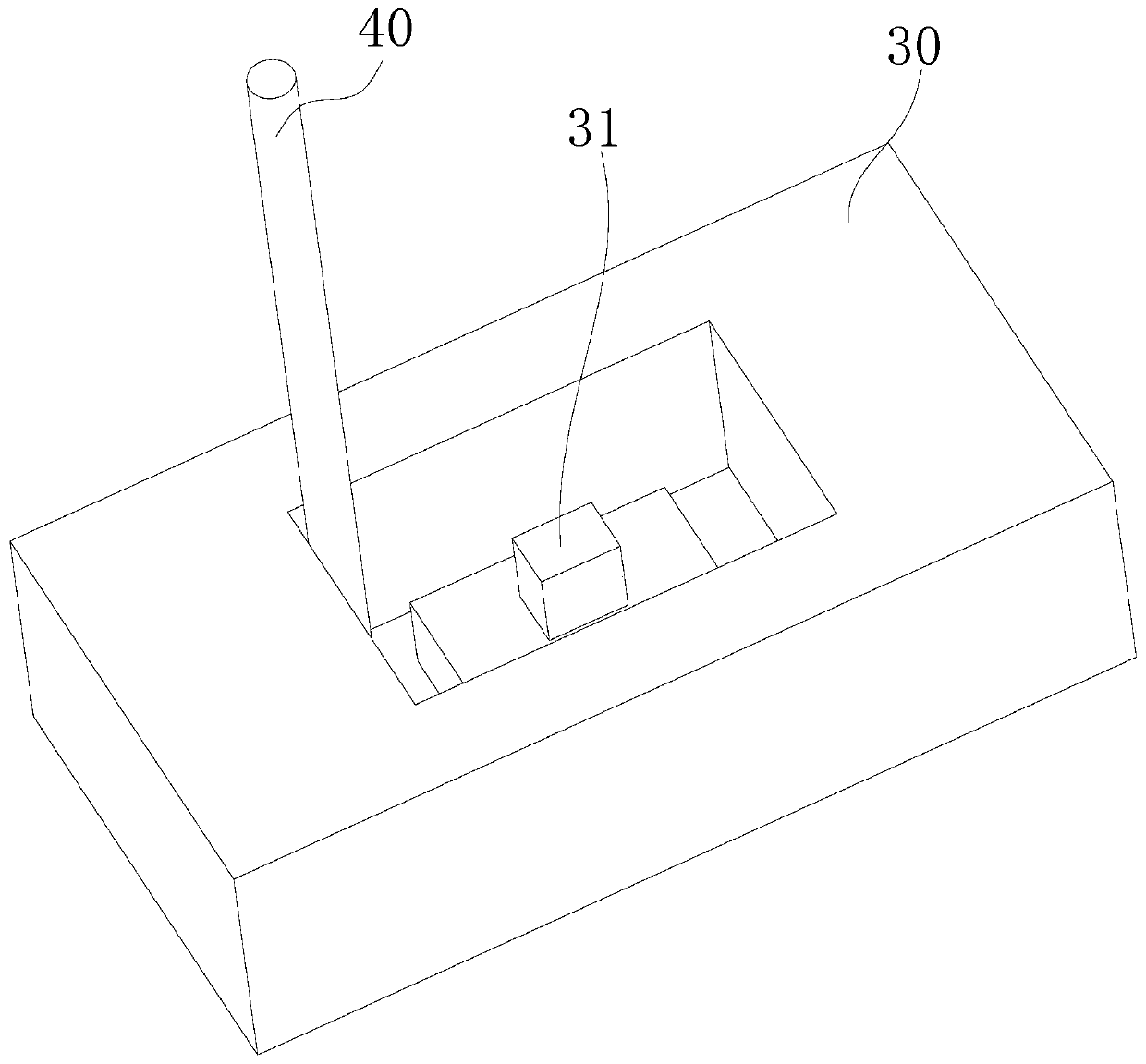
technical field [0001] The invention belongs to the technical field of micro electrolytic machining, and in particular relates to a micro electrolytic machining electrode, a processing method thereof, and a micro electrolytic machining device. Background technique [0002] Micro-electrolytic machining is a machining method based on electrochemical reactions to dissolve anodic workpieces to process three-dimensional microstructures. The tool electrode has no loss, can avoid defects such as fused layer, heat-affected zone and residual stress after machining, EDM and laser processing, and can process conductive materials of any strength and hardness. refer to figure 1 As shown, for the three-dimensional microstructure 31 on the micro-electrolytic machining workpiece 30, the micro-columnar electrode 40 is currently mainly used for layer-by-layer scanning electrolytic machining. Due to the small cross-sectional size of the micro-columnar electrode 40, its anti-interference abil...

Claims


Application Information

Patent Timeline
IPC IPC(8): B23H3/04B23H3/00
CPCB23H3/04B23H3/00
Inventor 雷建国伍晓宇徐斌周志文江凯朱立宽
Owner SHENZHEN UNIV
Learn More