Intelligent manipulator with rotating and clamping functions

A technology of intelligent manipulators and functions, applied in the direction of manipulators, program-controlled manipulators, chucks, etc., can solve the problems that manipulators cannot be realized, and achieve the effects of automatic operation, labor-saving and convenient operation

Pending Publication Date: 2020-05-22
SUZHOU JODELL ROBOTICS CO LTD
View PDF20 Cites 3 Cited by
  • Summary
  • Abstract
  • Description
  • Claims
  • Application Information

AI Technical Summary

Problems solved by technology

At present, most manipulators on the market only have the function of gripping objects, and need external arms or parts to realize the function of rotation. In som

Method used


Image

  • Intelligent manipulator with rotating and clamping functions
  • Intelligent manipulator with rotating and clamping functions
  • Intelligent manipulator with rotating and clamping functions

Examples


Example Embodiment

[0022] Embodiment one

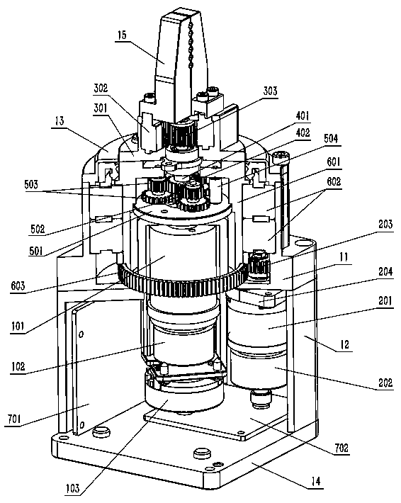
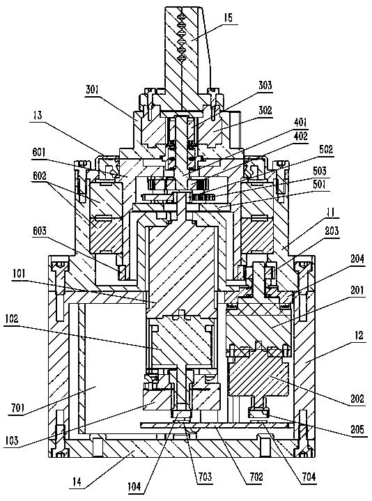
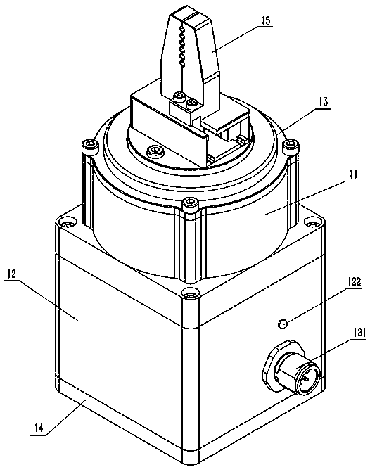
[0023] like Figure 1-3 As shown, a kind of intelligent manipulator with rotating and gripping function, comprises the rear cover 14, lower case 12, upper case 11, upper cover 13 and finger piece 15 that are connected successively from bottom to top, and described back cover 14. The lower housing 12, the upper housing 11, and the upper cover 13 form a space cavity. The upper housing 11 is connected with a conversion device, which passes through the upper cover 13 and is fixedly connected with the finger piece 15. The conversion device A cylindrical rotating frame 601 is arranged below, and the conversion device is connected with a rotating shaft 401. The lower shaft end of the rotating shaft 401 is provided with a shaft end gear 402, and the shaft end gear 402 is connected with a gear assembly structure. A first reducer 101 is connected, a first motor 102 is provided under the first reducer 101, a brake 103 is provided below the first motor 102, and a ...

Example Embodiment

[0036] Embodiment two

[0037] An intelligent manipulator with rotation and clamping functions differs from Embodiment 1 in that a physical limit structure that cooperates with each other is provided at the corresponding positions of the upper housing 11 and the rack guide groove 301, or the upper The corresponding positions of the housing 11 and the cylindrical rotating frame 601 are provided with a physical limiting structure that cooperates with each other to realize the rotation limiting of the cylindrical rotating frame 601. The angle of the physical limiting structure can be from 0° to 360° to complete the positioning The limit function of any rotation angle position.

[0038] Preferably, the physical limit structure can adopt stoppers that cooperate with each other to achieve precise rotation limit.

[0039]The working principle of the intelligent manipulator with rotation and gripping functions of the present invention:

[0040] 1. Clamping movement:

[0041] 1) The...


PUM


Abstract

The invention discloses an intelligent manipulator with rotating and clamping functions. The intelligent manipulator comprises a rear cover, a lower shell, an upper shell, an upper cover and a fingerpiece which are sequentially connected from bottom to top, wherein the upper shell is connected with a conversion device, and the conversion device is fixedly connected with the finger piece; a cylindrical rotating frame and a gear assembly structure are arranged below the conversion device, wherein a first speed reducer, a first motor and a brake are arranged below the gear assembly structure; and a second speed reducer, a second motor and a control unit are arranged in the lower shell. The intelligent manipulator has the beneficial effects that the functions of clamping and rotating objectsin the same manipulator product are achieved, application scenes that a user clamps and rotates the objects can be met, additional configuration is not needed, and manual operation is completely replaced by the manipulator at a certain station, so that operation convenience is brought, and meanwhile procedures and working hours are saved, and automatic operation is achieved.

Description

technical field [0001] The invention relates to the technical field of robot end grippers and manipulators, in particular to an intelligent manipulator with rotation and gripping functions. Background technique [0002] With the rapid development of the machinery industry, artificial intelligence is also developing rapidly, and intelligent machinery is gradually replacing manual operations, such as intelligent robots and intelligent manipulators. At present, most manipulators on the market only have the function of gripping objects, and need external arms or parts to realize the function of rotation. In some occasions, it is necessary to perform a necessary rotation operation on the gripped objects, but most of the existing manipulators cannot to achieve this function. Therefore, the manipulator grabs the object and rotates the object at a specific angle, which is required by modern industry. Contents of the invention [0003] The object of the present invention is to pr...

Claims


Application Information

Patent Timeline
IPC IPC(8): B25J9/04B25J9/10B25J15/02B25J15/08
CPCB25J9/04B25J9/1035B25J15/026B25J15/08
Inventor 郭海介党阳张伟禹超刘璐曹磊
Owner SUZHOU JODELL ROBOTICS CO LTD
Why Eureka
Try Eureka