Check patentability & draft patents in minutes with Patsnap Eureka AI!

Sputtering Apparatus and Method for Controlling Sputtering Apparatus

A technology of a sputtering device and a control method, applied in the directions of sputtering coating, final product manufacturing, sustainable manufacturing/processing, etc., can solve the problems of reduced film uniformity, reduced target service life, reduced operation rate, etc. Improve the effect of increasing the total usage, prolong the service life, and increase the effect of increasing the total usage

Active Publication Date: 2020-05-22
AVACO
View PDF6 Cites 0 Cited by
  • Summary
  • Abstract
  • Description
  • Claims
  • Application Information

AI Technical Summary

Problems solved by technology

[0006] First, due to the difference in the intensity of the plasma in different regions of the sputtering device of the prior art, the difference in erosion rate will occur according to the different parts of the target
Therefore, the sputtering apparatus of the prior art has a problem in that the remaining usable part is also unusable due to the most eroded part of the target.
Therefore, in the prior art sputtering apparatus, as the total usage amount of the target is reduced, the service life of the target is reduced, thus resulting in an increase in process cost due to replacement of the target and the like.
In addition, the prior art sputtering apparatus shortens the replacement cycle of the target, the time required to stop the overall process due to the replacement of the target increases, and thus the productivity of substrates that complete the sputtering process is reduced due to a decrease in the operation rate. reduce
[0007] Second, because the sputtering device in the prior art has different plasma intensity according to different regions, the difference in evaporation rate of the film will occur according to different parts of the substrate
Therefore, the sputtering device of the prior art has the problem that the uniformity of the thin film deposited on the substrate is reduced, and the quality of the substrate after the sputtering process is reduced.

Method used


Image

  • Sputtering Apparatus and Method for Controlling Sputtering Apparatus
  • Sputtering Apparatus and Method for Controlling Sputtering Apparatus
  • Sputtering Apparatus and Method for Controlling Sputtering Apparatus

Examples


Embodiment Construction

[0038] Hereinafter, embodiments of the sputtering apparatus of the present invention will be described in detail with reference to the drawings.

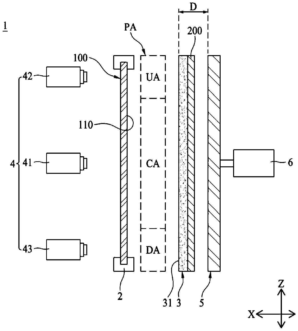
[0039] refer to figure 1 , the sputtering apparatus 1 of the present invention performs a sputtering process on a substrate 100 for manufacturing a display device, a solar cell (Solar Cell), a semiconductor device, and the like. The sputtering device 1 of the present invention includes a support unit 2 , a target 3 , an acquisition unit 4 , a magnet unit 5 , and a moving unit 6 .

[0040] refer to figure 1, the supporting part 2 is used to support the substrate 100 . The supporting part 2 can support the substrate 100 such that the substrate 100 stands parallel to the up-down direction (Z-axis direction). The supporting part 2 can respectively support the upper end of the substrate 100 and the lower end of the substrate 100 based on the vertical direction (Z-axis direction). The support unit 2 may be disposed between the acquisi...


PUM


Abstract

The invention relates to a sputtering apparatus and a method for controlling the sputtering apparatus. The sputtering appratus includes: a support unit for supporting a substrate; a target which is arranged separately from the support unit in a first axial direction; an acquisition unit that is used to measure the intensity of the plasma generated between the substrate supported by the support unit and the target with the first axis direction as a reference to acquire the plasma value; a magnet unit which is used for regulating the intensity of plasma; and a moving unit which is for moving themagnet unit along the first axis direction, wherein the moving unit moves the magnet unit along the first axis direction so as to adjust at least one of the plurality of medium plasma values, the plurality of upper plasma values, and a plurality of lower plasma values with the maximum medium plasma value among the plurality of medium plasma values as a reference.

Description

technical field [0001] The invention relates to a sputtering device and a control method of the sputtering device for performing a sputtering process such as an evaporation process on a substrate. Background technique [0002] Generally, in order to manufacture a display device, a solar cell (Solar Cell), a semiconductor device, etc., a predetermined thin film layer, a thin film circuit pattern, or an optical pattern should be formed on a substrate. For this purpose, the substrate is subjected to a treatment process, for example, an evaporation process for evaporating a thin film of a specific material on the substrate, a photolithography process for selectively exposing the thin film using a photosensitive material, removing the selectively exposed part of the thin film to Etching process for patterning etc. [0003] Like this, sputtering equipment is equipped to process the substrate. The sputtering device mainly implements the evaporation process of evaporating thin fil...

Claims


Application Information

Patent Timeline
Patent Type & Authority Applications(China)
IPC IPC(8): C23C14/54C23C14/35C23C14/24
CPCC23C14/54C23C14/35C23C14/24Y02P70/50
Inventor 朴瑨哲
Owner AVACO
Features
  • R&D
  • Intellectual Property
  • Life Sciences
  • Materials
  • Tech Scout
  • Unparalleled Data Quality
  • Higher Quality Content
  • 60% Fewer Hallucinations
Learn More